Adjustable screwdriver structure

A screwdriver structure and adjustable technology, which is applied to screwdrivers, wrenches, wrench, etc., can solve the problems of operating screwdrivers, such as safety impact and lack of convenience

Inactive Publication Date: 2007-05-16
谢智庆
View PDF0 Cites 3 Cited by
  • Summary
  • Abstract
  • Description
  • Claims
  • Application Information

AI Technical Summary

Problems solved by technology

[0004] The above-mentioned screwdriver structure only has two lengths available for use. For users, it lacks the convenience of using more variety of lengths to choose from.
Moreover, when the user turns the screwdriver, he often applies a large axial thrust due to carelessness, causing the steel ball 622 originally positioned in the upper groove 72 to slide to the lower groove 73 due to compression, Therefore, it has a considerable impact on the safety of the user's operation of the screwdriver.

Method used


Image

  • Adjustable screwdriver structure
  • Adjustable screwdriver structure
  • Adjustable screwdriver structure

Examples


Embodiment Construction

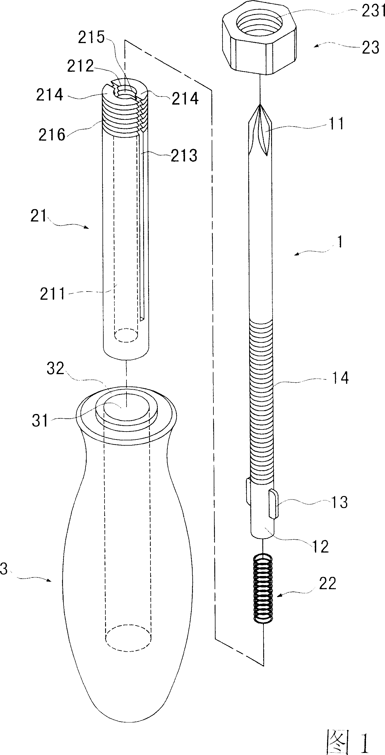
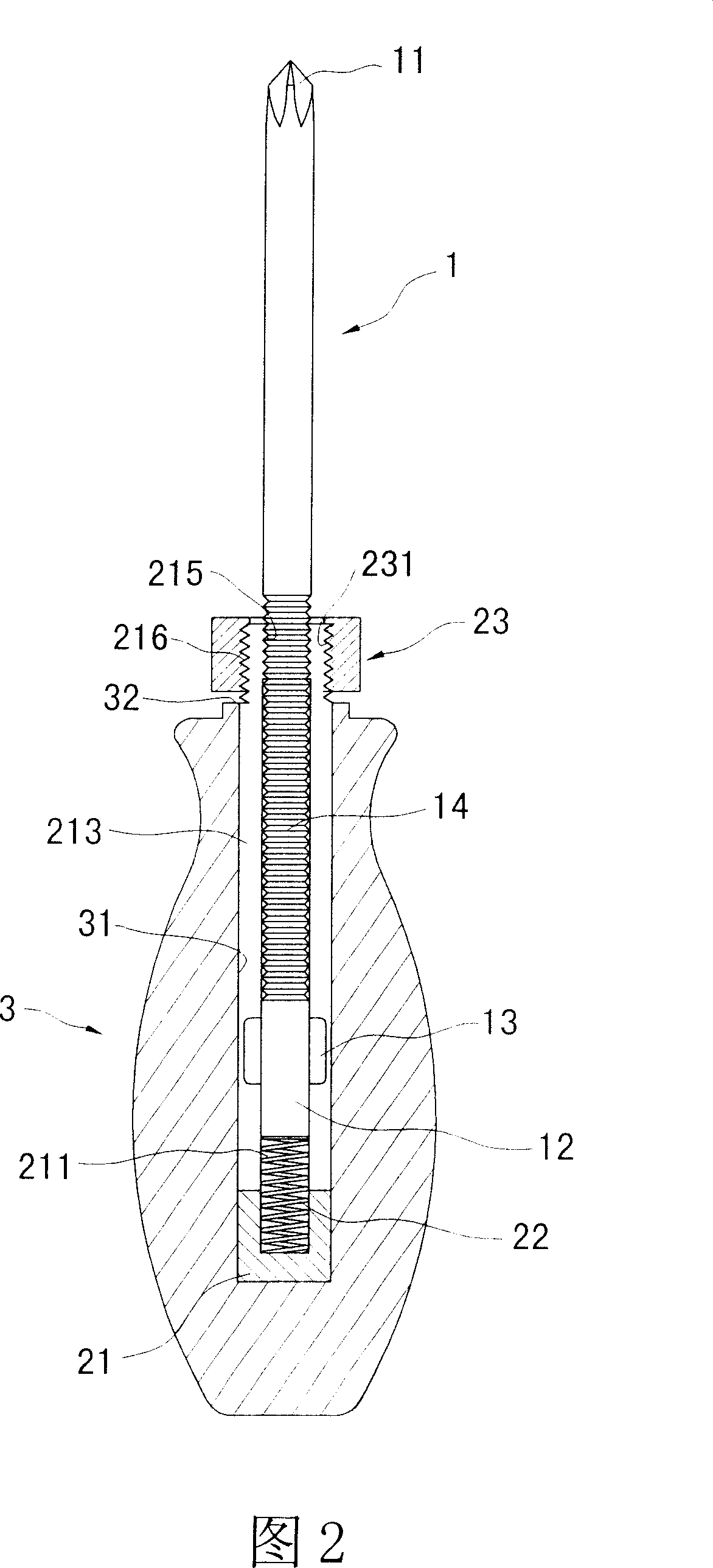
[0019] Referring to Fig. 1 to Fig. 2, the structure of the selected embodiment of the present invention is shown in the figure.

[0020] The adjustable screwdriver structure of the present embodiment includes:

[0021] A rod body 1, one end is a screw driver head 11, the screw driver head 11 is a cross screwdriver head in this embodiment, the other end of the rod body 1 has a socket section 12, and the rod body 1 is protrudingly arranged adjacent to the socket section 12 There are two symmetrical stoppers 13, and the rod body 1 has a stopper section 14 on the periphery. In this embodiment, the stopper section 14 is an external thread section.

[0022] A clamping part includes a rod 21, an elastic component 22 and an urging component 23, the urging component 23 is a nut in this embodiment, and the elastic component 22 is a compression spring in this embodiment . Wherein, the rod 21 has an accommodating space 211, and the rod 21 is provided with an opening 212 at one end of th...


PUM


Abstract

The invention relates to an adjustable screw driver structure, which comprises a rod, a clamper and a handle, wherein one end of rod is screw driving head, another end is sheathing section; the clamper comprises rod, flexible element and compression element; the rod has a container with an axial groove with two blocks, to divide the rod into two elastic sheets, and its inner edge has a clamping section, and its open end has an outer screw section; the flexible element is through the container to contact the bottom of container; two blocks are through two open grooves of rod; the rod sheathing section is through the container; when compression element is screwed with rod, the elastic sheets will be bended inwards, to make clamping section clamp the stop section of rod; the rod is fixed to one axial hole of handle. The invention can improve safety.

Description

technical field [0001] The invention relates to an adjustable screwdriver structure. Background technique [0002] As shown in Figure 3, it is an existing screwdriver structure, including a rod body 6 and a handle 7, the handle 7 has an accommodating space 71, and the accommodating space 71 has two upper and lower grooves 72 on the inner wall , 73, and one end of the rod body 6 is a cross screwdriver head 61 for use, and the end of the rod body 6 away from the cross screwdriver head 61 has an alcove 62 on the periphery, and the alcove 62 is equipped with an elastic component 621 and a positioning The steel ball 622 used. [0003] When the user intends to use it, the steel ball 622 must first be pressed into the alcove 62 and then the rod body 6 is placed into the accommodating space 71 for sliding. When the steel ball 622 slides to the upper groove 72 of the accommodating space 71 of the handle 7 , it pops up and is positioned against the upper groove 72 . If the rod body...

Claims


Application Information

Patent Timeline
Patent Type & Authority Applications(China)
IPC IPC(8): B25B15/00B25B23/16B25B23/00
Inventor 谢智庆
Owner 谢智庆
Why Eureka
Try Eureka