
Cleaning robot with fan brake device

A technology for cleaning robots and braking devices, which is applied in the field of cleaning robots and can solve problems such as danger to users

Inactive Publication Date: 2021-06-01
燕成祥
View PDF10 Cites 0 Cited by
  • Summary
  • Abstract
  • Description
  • Claims
  • Application Information

AI Technical Summary

Problems solved by technology

[0003] At present, cleaning robots are all equipped with a fan between the dust suction port and the dust collection box to suck the dust into the dust collection box through the suction port through the suction force generated by the fan. When removing the dust box, the power of the cleaning robot must be completely turned off before the dust box can be removed and replaced, so as to prevent the danger to the user due to the fan still rotating when the dust box is removed.

Method used


Image

  • Cleaning robot with fan brake device
  • Cleaning robot with fan brake device
  • Cleaning robot with fan brake device

Examples


Embodiment Construction

[0026] In order for those skilled in the art to understand the technical features, content and advantages of the present invention and the effects that can be achieved, the present invention is hereby combined with the accompanying drawings and appendices, and is described in detail in the form of embodiments as follows, and the used The purpose of the diagrams is only for illustration and auxiliary instructions, and may not be the true proportion and precise configuration after the implementation of the present invention. Therefore, the proportion and configuration relationship of the attached diagrams should not be interpreted or limited to the actual implementation of the present invention. The scope of rights shall be described first.

[0027] In describing the present invention, it should be understood that the terms "center", "transverse", "upper", "lower", "left", "right", "top", "bottom", "inner", " The orientation or positional relationship indicated by "outside", etc...


PUM


Abstract

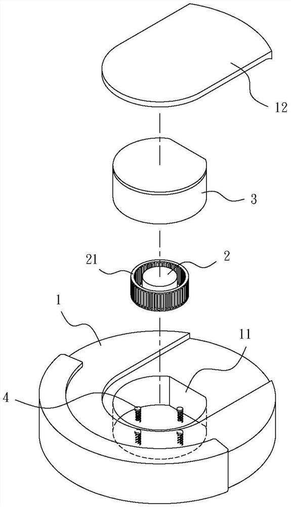
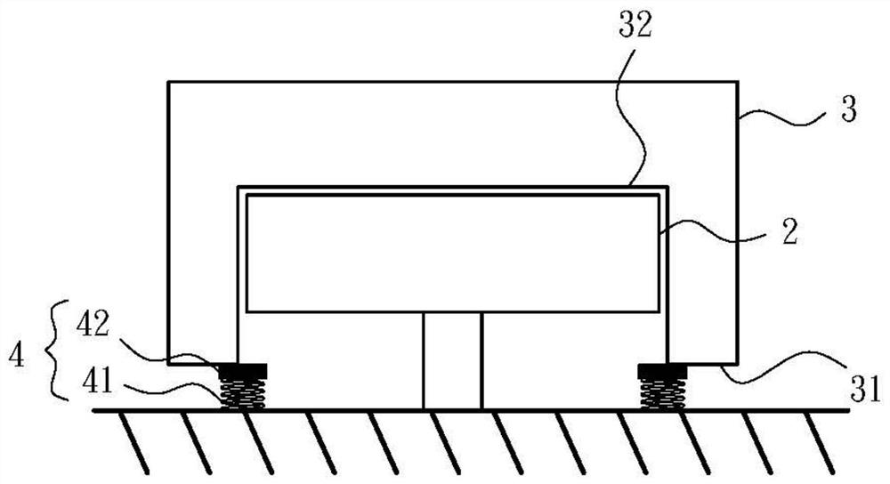
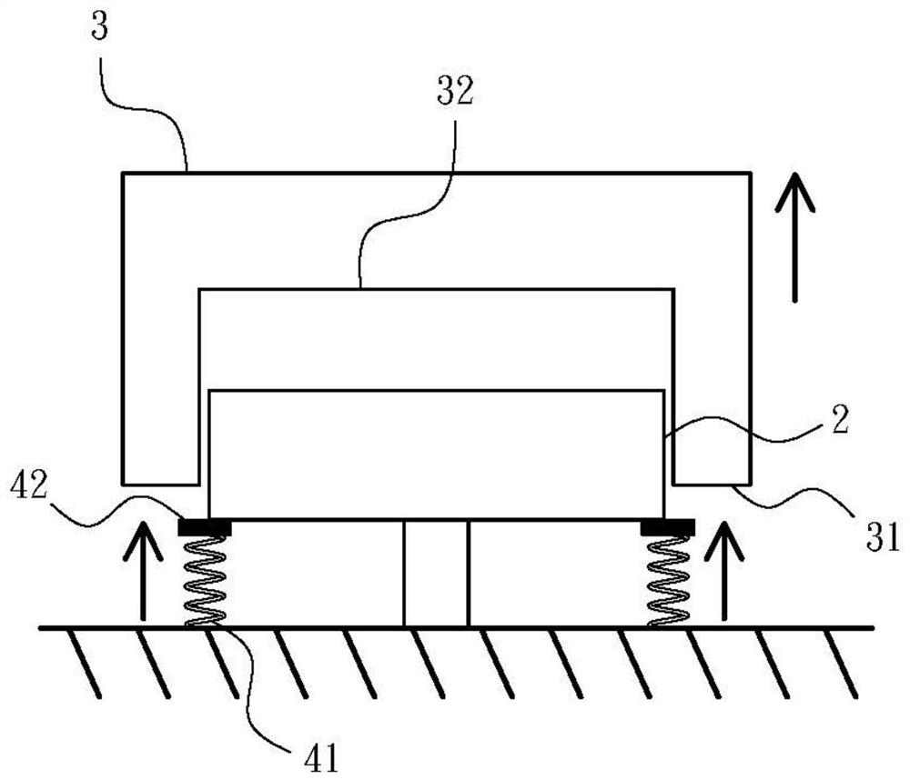
The invention provides a cleaning robot with a fan brake device, which is mainly characterized in that at least one brake device is arranged in an accommodating groove of a cleaning machine body for accommodating a dust collecting box and a fan, and the brake device is a concave part which is positioned at the bottom of the dust collecting box and is used for embedding the fan and is positioned below a junction position of the bottom of the dust collecting box; when the dust collection box is taken down, the soft blocking piece is pushed upwards through the elastic force of the elastic element in the brake device, the soft blocking piece abuts against the lower portion of fan blades of the fan so as to stop rotation of the fan, and when the dust collection box is installed in the containing groove of the cleaning machine body, the brake device is pressed downwards through the bottom of the dust collection box so that the fan can be separated from the soft blocking piece. Therefore, through the arrangement of the brake device, the danger caused by continuous rotation of the fan after the dust collection box is taken down can be avoided.

Description

technical field [0001] The invention relates to a cleaning robot, especially a cleaning robot with a fan brake device. Background technique [0002] The cleaning robot is a cleaning device that can move on the ground and clean the ground by itself. There is a cleaning brush at the bottom of the cleaning robot, which is used to collect the dust on the ground that it walks on, and then the dust is sucked by the suction at the bottom of the cleaning robot. The dust port sucks in the dust collecting box set inside it. [0003] At present, cleaning robots are all equipped with a fan between the dust suction port and the dust collection box to suck the dust into the dust collection box through the suction port through the suction force generated by the fan. When removing the dust box, the power of the cleaning robot must be completely turned off before the dust box can be removed and replaced, so as to prevent the danger to the user due to the fan still rotating when the dust box...

Claims


Application Information

Patent Timeline
IPC IPC(8): A47L11/24A47L11/40
CPCA47L11/24A47L11/40A47L11/4013
Inventor 燕成祥
Owner 燕成祥
Learn More