Metal detection device
A metal detection and metal technology, which is used in measuring devices, geophysical measurements, radio wave measurement systems, etc., can solve problems such as inability to tune, achieve efficient inspection, and improve detection sensitivity.
- Summary
- Abstract
- Description
- Claims
- Application Information
AI Technical Summary
Problems solved by technology
Method used
Image

Examples
Embodiment 1
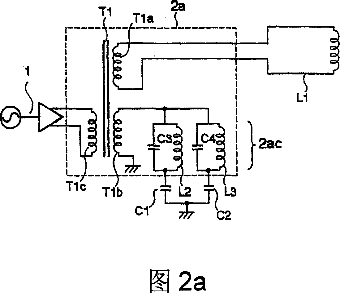
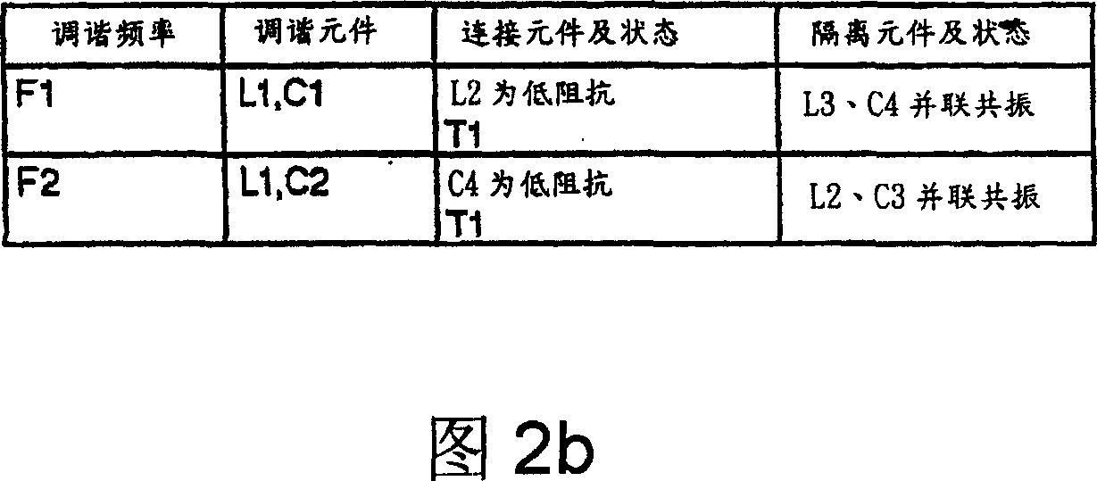
[0059] FIG. 2( a ) is a schematic diagram of the electrical structure of an example of the magnetic field generating unit 2 of this embodiment. FIG. 2(b) shows the main functions and actions of each constituent element. The tuning element in Fig. 2(b) and the connection elements that contribute to the tuning function are the main components of the tuning function part, and the isolation element is the main part of the isolation function part (hereinafter, Fig. 3(b), Fig. 3(c), The same applies to Fig. 4(b) and Fig. 5(b)).
[0060] In FIG. 2( a ), the signal generating unit 1 inputs a signal (F1<F2) including frequency components F1 and F2 to the magnetic field generating unit 2 through the coils T1c and T1b of the transformer T1. The dotted line portion in Fig. 2(a) indicates the connection portion 2a. In FIG. 2( a ), values are set such that the coil L2 and the capacitor C3 resonate in parallel at the frequency F2, and the coil L3 and the capacitor C4 resonate in parallel...
Embodiment 2
[0064] FIG. 3( a ) is a schematic diagram of the electrical structure of another embodiment of the magnetic field generating unit 2 .
[0065] Fig. 3 (b) shows that the frequency of the signal of the frequency F1 component output by the signal generation unit 1a in Fig. 3 (a) is lower than the frequency of the signal of the frequency F2 component output by the signal generation unit 1b (F1F2), each structure The main functions and functions of components. In FIG. 3( a ), the signal generators 1 a and 1 b input the signal of the frequency F1 component and the signal of the frequency F2 component to the magnetic field generator 2 via transformers T2 and T3 , respectively.
[0066] Below, according to Fig. 3(a) and Fig. 3(b), the situation (F1
Embodiment 3
[0070] FIG. 4( a ) is a schematic diagram of the electrical structure of another embodiment of the magnetic field generating unit 2 . FIG. 4(b) shows the main functions and actions of each constituent element. In Fig. 4, the signal generating units 1a and 1b input the signal of the frequency F1 component and the signal of the frequency F2 component (F1<F2 in this example) to the magnetic field generating unit 2 through the capacitor C1 and the transformer T2, the capacitor C2 and the transformer T3 respectively. . Among them, the impedance of the signal generation unit 1a viewed from the capacitor C1 and the impedance of the signal generation unit 1b viewed from the capacitor C2 are low at least at their respective frequencies.
[0071] In FIG. 4, in the frequency F1 region, the transmitting coil L1 is tuned so as to be connected to the capacitor C1 via the coil L8 and the transformer T4 (at this time, L1+L8 and C1 resonate), thereby constituting the F1 tuning function part 2...
PUM
 Abstract
Description
Claims
Application Information
 - R&D
- Intellectual Property
- Life Sciences
- Materials
- Tech Scout
- Unparalleled Data Quality
- Higher Quality Content
- 60% Fewer Hallucinations
Browse by: Latest US Patents, China's latest patents, Technical Efficacy Thesaurus, Application Domain, Technology Topic, Popular Technical Reports.
© 2025 PatSnap. All rights reserved.Legal|Privacy policy|Modern Slavery Act Transparency Statement|Sitemap|About US| Contact US: help@patsnap.com