
Phase current detector

A detection device and current detector technology, which is applied in the direction of output power conversion device, electrical components, AC power input conversion to DC power output, etc., can solve the problems of reduced operating range, abnormal noise, and difficulty in reducing ringing, etc., to achieve Effects of improving current detection accuracy, reducing measurement error, and improving current measurement accuracy

Inactive Publication Date: 2007-04-25
DAIKIN IND LTD
View PDF0 Cites 7 Cited by
  • Summary
  • Abstract
  • Description
  • Claims
  • Application Information

AI Technical Summary

Problems solved by technology

[0004] When the above structure is adopted, the following disadvantages occur, namely: current measurement error caused by ringing, waveform distortion caused by prolongation of pulse output time, reduction of operating range, generation of abnormal noise, etc.
[0005] In particular, since no solution for ringing is proposed, there are disadvantages that it is difficult to reduce ringing, high-speed response cannot be performed, or measurement accuracy cannot be improved.
[0006] Also, although it is considered that a parallel resistor can be used to detect the pulse current flowing through the DC link, it is difficult to reduce the influence of noise and improve the measurement accuracy, and there is a problem that it cannot be detected for pulses other than long pulses due to the peak voltage caused by the inductance of the parallel resistor. Bad Cases of Current Sensing with Pulse
Therefore, the use of parallel resistors to detect phase currents has not yet reached practicality

Method used


Image

  • Phase current detector
  • Phase current detector
  • Phase current detector

Examples


Embodiment Construction

[0098] Embodiments of the phase current detection device of the present invention will be described in detail below with reference to the accompanying drawings.

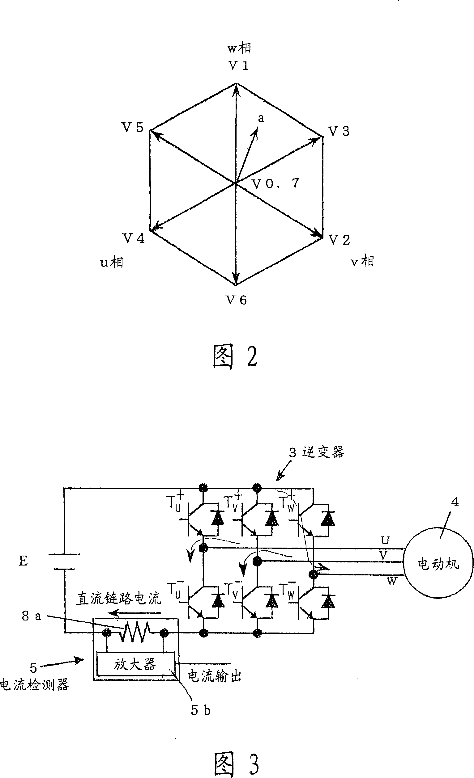
[0099] FIG. 1 is a diagram showing the configuration of a motor drive device using an inverter. Table 1 shows the relationship between the output voltage vector of the inverter (power device) and the switching state of the switching element.

[0100] Table 1

[0101] T u +

T v +

T w +

V0

V1

V2

V3

V4

V5

V6

V7

OFF

OFF

OFF

OFF

ON

ON

ON

ON

OFF

OFF

ON

ON

OFF

OFF

ON

ON

OFF

ON

OFF

ON

OFF

ON

OFF

ON

[0102] Among them, T u + , T v + , T w + represent the switching elements of the upper bridge arms of the u-phase, v-phase, and w-phase respectively, T u - , T v - , T ...


PUM


Abstract

A first capacitor (2a) is connected between the output terminals of a rectification circuit (2) the input of which is an AC power source (1), and a three-phase inverter (3) in parallel with the first capacitor (2a), and the output of the three-phase inverter (3) is supplied to a motor (4). A second capacitor (3a) is connected in parallel with the input side of the three-phase inverter (3), a current detector (5) between the first capacitor (2a) and second capacitor (3a), and a third capacitor in parallel with the first capacitor (2a) slightly closer to the power source than to the current detector (5). Thus, the capacitance of the second capacitor (3a) is set as small as possible in such a range that a power device is not broken down by a surge voltage attributed to switching to suppress ringing, so that current is incorporated at a high speed with a high precision.

Description

[0001] This application is a divisional application of the original patent application number 02802758.2 (international application number: PCT / JP02 / 09901, filing date: September 25, 2002, invention name: phase current detection device). technical field [0002] The present invention relates to a phase current detection device that detects a motor based on a current of a DC link and an additional vector diagram in a motor drive device that supplies an output from a PWM inverter to a motor and drives the motor phase current. Background technique [0003] Conventionally, in a motor drive device in which an inverter drives a motor, a device for deforming an output pulse into a measurable output has been proposed as a device for detecting a motor phase current. [0004] When the above-mentioned structure is adopted, the following disadvantages occur, namely, current measurement error due to ringing, waveform distortion due to extension of pulse output time, reduction of operatin...

Claims


Application Information

Patent Timeline
Patent Type & Authority Applications(China)
IPC IPC(8): H02M7/5387H02M7/5395
Inventor 前田敏行谷口智勇
Owner DAIKIN IND LTD
Learn More