
Method and apparatus for digital signal processing

A digital signal processing and digital signal technology, applied in the field of digital signals, can solve the problems of slow reduction of interference energy, inability to increase indefinitely, and limitation of main clock frequency performance, so as to achieve suppression of spectral aliasing interference, suppression of adjacent band interference, The effect of improving representation accuracy

Active Publication Date: 2007-04-18
HUAWEI TECH CO LTD
View PDF0 Cites 0 Cited by
  • Summary
  • Abstract
  • Description
  • Claims
  • Application Information

AI Technical Summary

Problems solved by technology

However, the main clock frequency is limited by the performance of the device and cannot be increased infinitely.
Moreover, the interference energy decreases slowly with the increase of the main clock frequency, so by increasing the main clock frequency to reduce the interference energy, the signal-to-noise ratio is difficult to meet the signal-to-noise ratio requirements of high-order modulation methods, and at the same time, the data rate and frequency range is wide Adjustable is also difficult to achieve

Method used


Image

  • Method and apparatus for digital signal processing
  • Method and apparatus for digital signal processing
  • Method and apparatus for digital signal processing

Examples


no. 1 example

[0029] The first embodiment of the digital signal processing method provided by the present invention includes the following steps:

[0030] Step 1: When each master clock pulse arrives, the value Vrem is accumulated once, and the accumulated result Vrem=Vrem+frequency word FW, wherein FW=the frequency Fs of the clock to be synthesized / the frequency change step size Fstep of the clock to be synthesized; wherein Vrem The initial value can be preset to any value.

[0031] Step 2: If Vrem

[0032] If Vrem≥CW, do modulo processing to Vrem, that is, Vrem=Vrem mod CW and go to step 3;

[0033] In order to realize the modulus processing conveniently, the initial value of Vrem can also be set to be less than 2*CW-FW, and the subtraction operation can be used to achieve the modulo processing effect, that is, Vrem=Vrem-CW, go to step 3.

[0034] Where CW=main clock Fm / frequency change step size Fstep of the clock to be synthesized.

[0035] Step 3: Output the Vrem a...


PUM


Abstract

The invention provides a digital signal processing method and device, reducing in-band interference and adjacent band interference of output signal on the condition that digital signal processing main clock frequency is not integral times as large as data clock frequency. And the invention mainly utilizes main clock sequence to synthesize data clock sequence and its time offset, utilizes the time offset and digital signal value to calculate transition value, inserts the transition value in the digital signal sequence to make step jumping on trapezoid holding signal waveform of the digital signal modified into slow transition of band middle values, and reduces spectrum mixing interference caused by main clock sampling.

Description

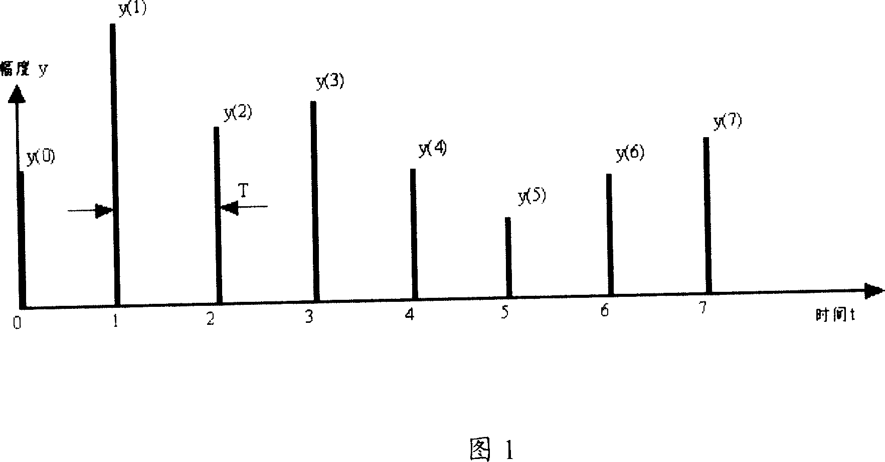
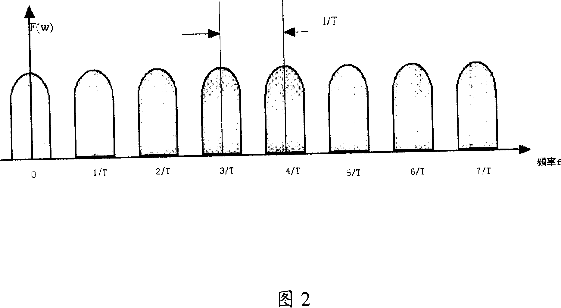
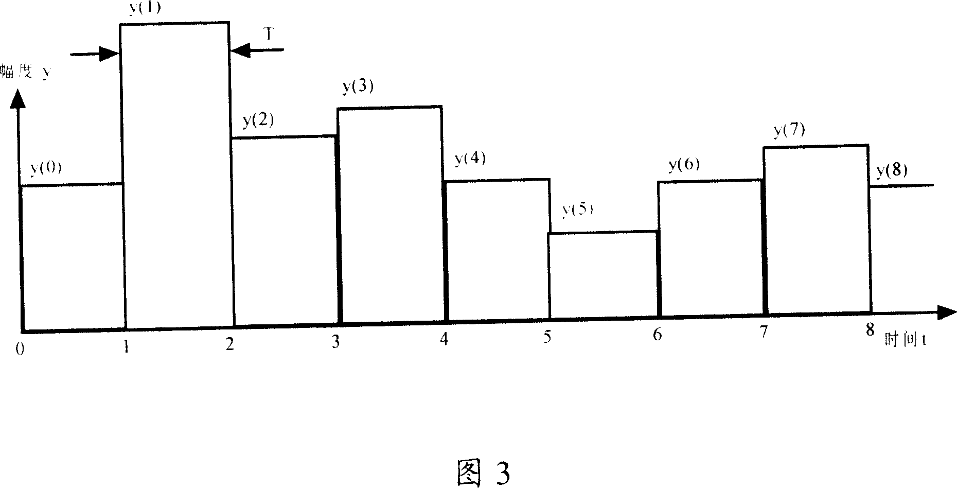
technical field [0001] The invention relates to digital signal technology, in particular to a digital signal processing method and device. Background technique [0002] As shown in Figure 1, it is a theoretical digital signal, the sampling interval is T (that is, the data rate is 1 / T), there is a signal amplitude impact at each sampling point, and the sampling points can be considered as 0 or undefined . [0003] The frequency spectrum of the above-mentioned digital signal is shown in FIG. 2 , and the spectrum lobe repeats at intervals of 1 / T period. This spectral shape is called a comb spectrum. [0004] A practical digital signal will not be an impulse response, usually as shown in Figure 3. The data sampling interval is T, the data changes at the sampling point, and the value at the previous sampling point is maintained between the sampling points. This kind of signal can be considered as the result of the ideal digital signal shown in Figure 1 passing through a filte...

Claims


Application Information

Patent Timeline
Patent Type & Authority Applications(China)
IPC IPC(8): H04L5/14G06F1/04
Inventor 贾学卿
Owner HUAWEI TECH CO LTD
Learn More