
Discontinuous mode PFC controller with energy-saving modulator and its operating method

A controller and mode technology, applied in the direction of climate sustainability, output power conversion device, irreversible AC power input conversion to DC power output, etc., can solve the problem that power converters are difficult to meet energy saving requirements, switching transistor switching loss buffering Inductor power consumption, increased loss of inductors, etc.

Inactive Publication Date: 2007-03-28
SYST GEN
View PDF0 Cites 39 Cited by
  • Summary
  • Abstract
  • Description
  • Claims
  • Application Information

AI Technical Summary

Problems solved by technology

Switching losses in power converters and PFC boosters are proportional to switching frequency, where switching losses in switching transistors, power dissipation in snubbers, and inductor losses increase with higher switching frequencies
The disadvantage of the previous controllers is that under high frequency operation under light load conditions, it is difficult for the power converter to meet the energy saving requirements. Therefore, especially for light load and no load conditions, it is desirable to provide a PFC controller that can operate at light loads Maintain PFC function and provide low power consumption

Method used


Image

  • Discontinuous mode PFC controller with energy-saving modulator and its operating method
  • Discontinuous mode PFC controller with energy-saving modulator and its operating method
  • Discontinuous mode PFC controller with energy-saving modulator and its operating method

Examples


Embodiment Construction

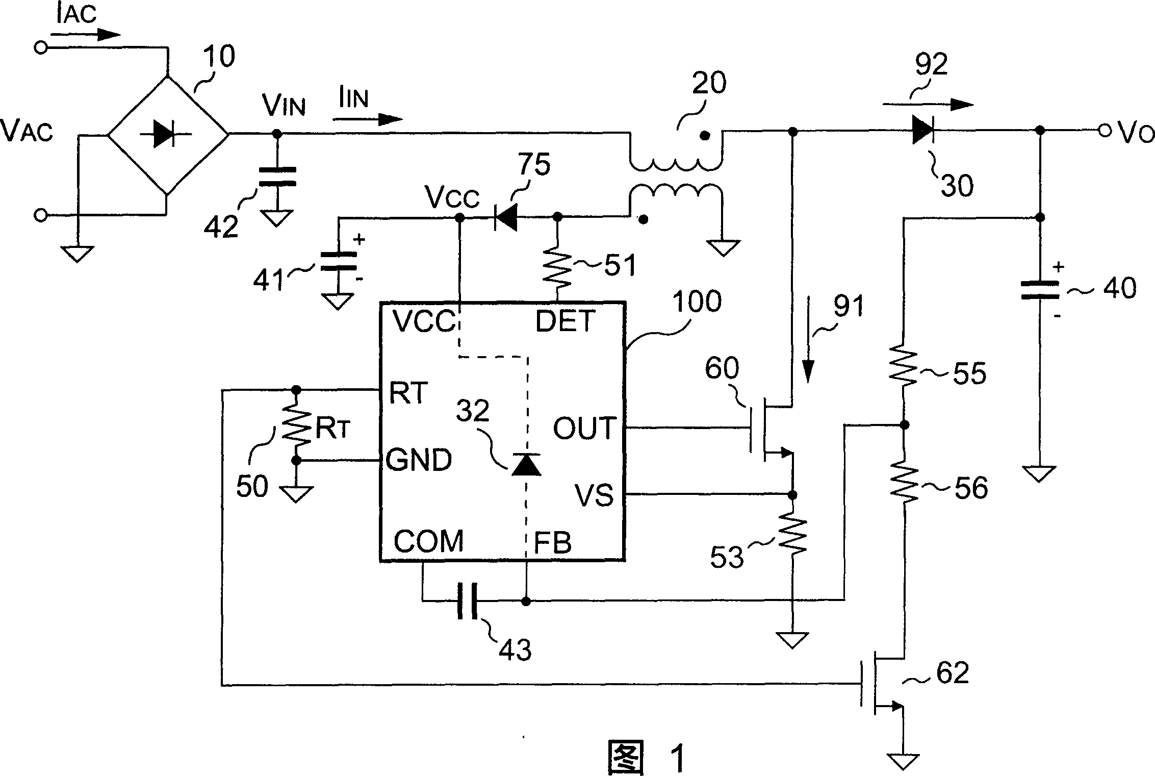
[0017] FIG. 1 is a schematic diagram of a discontinuous mode power factor correction (PFC) converter according to a preferred embodiment of the present invention. The PFC converter includes a bridge 10 , an inductor 20 , a rectifier 30 and a capacitor 40 . For feedback operation, the PFC converter further includes a controller 100 ; capacitors 41 and 43 ; resistors 50 , 51 and 53 ; a voltage divider including resistors 55 and 56 ; transistors 60 and 62 and a diode 75 . Through the PFC converter, the alternating current (AC) line input is converted into direct current (DC) output V O , where switching current 91 switches AC via input inductor 20 , rectifier 30 and capacitor 40 to control energy. The purpose of the PFC converter is to convert the AC line input current I AC The waveform control is sinusoidal and maintains I AC phase with the AC line input voltage V AC same. rectified via bridge 10, V IN Always positive with respect to ground of the PFC converter.

[0018] ...


PUM


Abstract

The present invention discloses a ZCS discontinuous mode PFC controller having a power saving modulator. The controller turns on through the feedback resistor and the parasitic diode of the controller, thus eliminating the need for a startup resistor. To achieve ZCS, the inductor current is released to zero, while the switching signal is off, before the next switching cycle starts. In order to decrease the switching frequency for light load conditions, an off-time delay is inserted right before the start of every switching cycle. The off-time delay is modulated to be the function of the feedback voltage and supply voltage. When the supply voltage is lower than the limit voltage, the off-time delay will decrease to inhibit the decrease of a switching frequency therefore prevents a low supply voltage. The switching frequency is decreased in accordance with the decrease of the load. Consequently, the switching losses and power consumption for light load and no load conditions are reduced.

Description

technical field [0001] The present invention relates to a power factor correction (power factor correction, PFC) controller and its operating method, in particular to a discontinuous mode PFC controller with an energy-saving modulator and its operating method. Background technique [0002] Most power factor correction techniques are integrated and utilize a boost topology, which can operate in both continuous and discontinuous inductor current modes at fixed or variable switching frequencies. Continuous inductor current mode operating at a fixed switching frequency is used for higher power applications due to the low peak current applied and operated. For applications below 250 watts, discontinuous inductor current mode operation with variable switching frequency offers several advantages, including small inductor size, low cost, simple circuitry, and zero current switching (ZCS). The pulse width of the power factor correction (PFC) controller is controlled by the voltage e...

Claims


Application Information

Patent Timeline
IPC IPC(8): H02M7/12H02M1/00H02M1/42
CPCY02B70/126H02M1/4225Y02B70/10
Inventor 杨大勇陈秋麟林振宇
Owner SYST GEN
Learn More