Eureka AIR delivers breakthrough ideas for toughest innovation challenges, trusted by R&D personnel around the world.

Lithographic method

A technology of lithography and lithography projection, applied in the field of lithography

Inactive Publication Date: 2007-03-28
ASML NETHERLANDS BV
View PDF3 Cites 7 Cited by
  • Summary
  • Abstract
  • Description
  • Claims
  • Application Information

AI Technical Summary

Problems solved by technology

Overlay errors can be caused by various causes, e.g. systematic errors in interferometric position or displacement measurement systems

Method used


Image

  • Lithographic method
  • Lithographic method
  • Lithographic method

Examples


Embodiment Construction

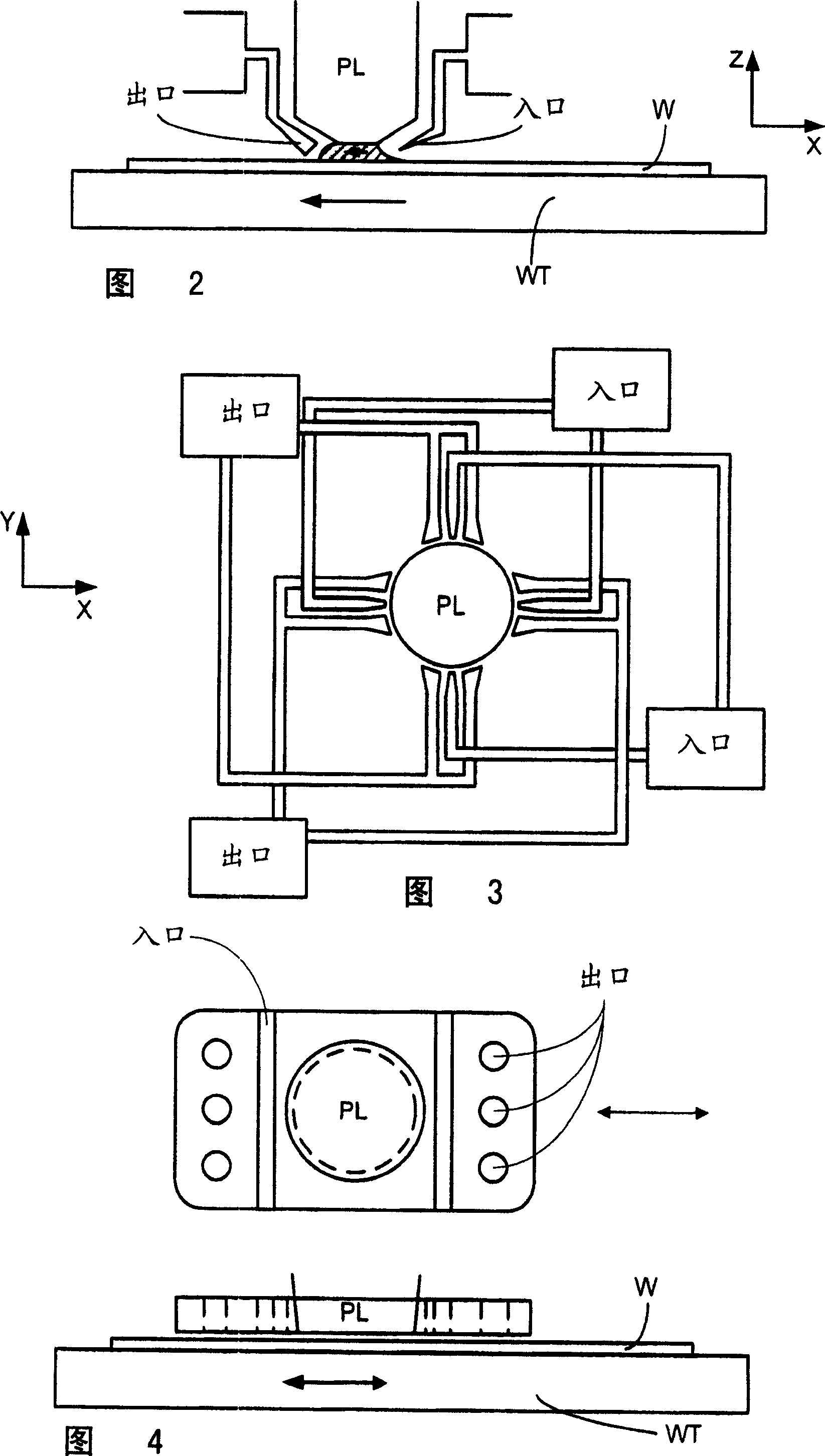
[0040] Figure 1 schematically depicts a lithographic apparatus that can be used in embodiments of the present invention. The equipment includes:

[0041] An illumination system (illuminator) IL configured to adjust the radiation beam PB (for example, UV radiation or DUV radiation);

[0042] Configured to support the patterning device (e.g., mask) MA and the supporting structure (e.g., mask table) MT connected to the first positioning device PM, the first positioning device being configured to accurately position the patterning device according to specific parameters;

[0043] It is configured to support a substrate (for example, a resist coated wafer) W and a substrate table (for example, a wafer table) WT connected to a second positioning device PW, which is set to accurately position the substrate according to certain parameters. Bottom; and

[0044] A projection system (e.g., a refractive projection lens system) PL configured to project the pattern imparted to the radiation bea...


PUM


Abstract

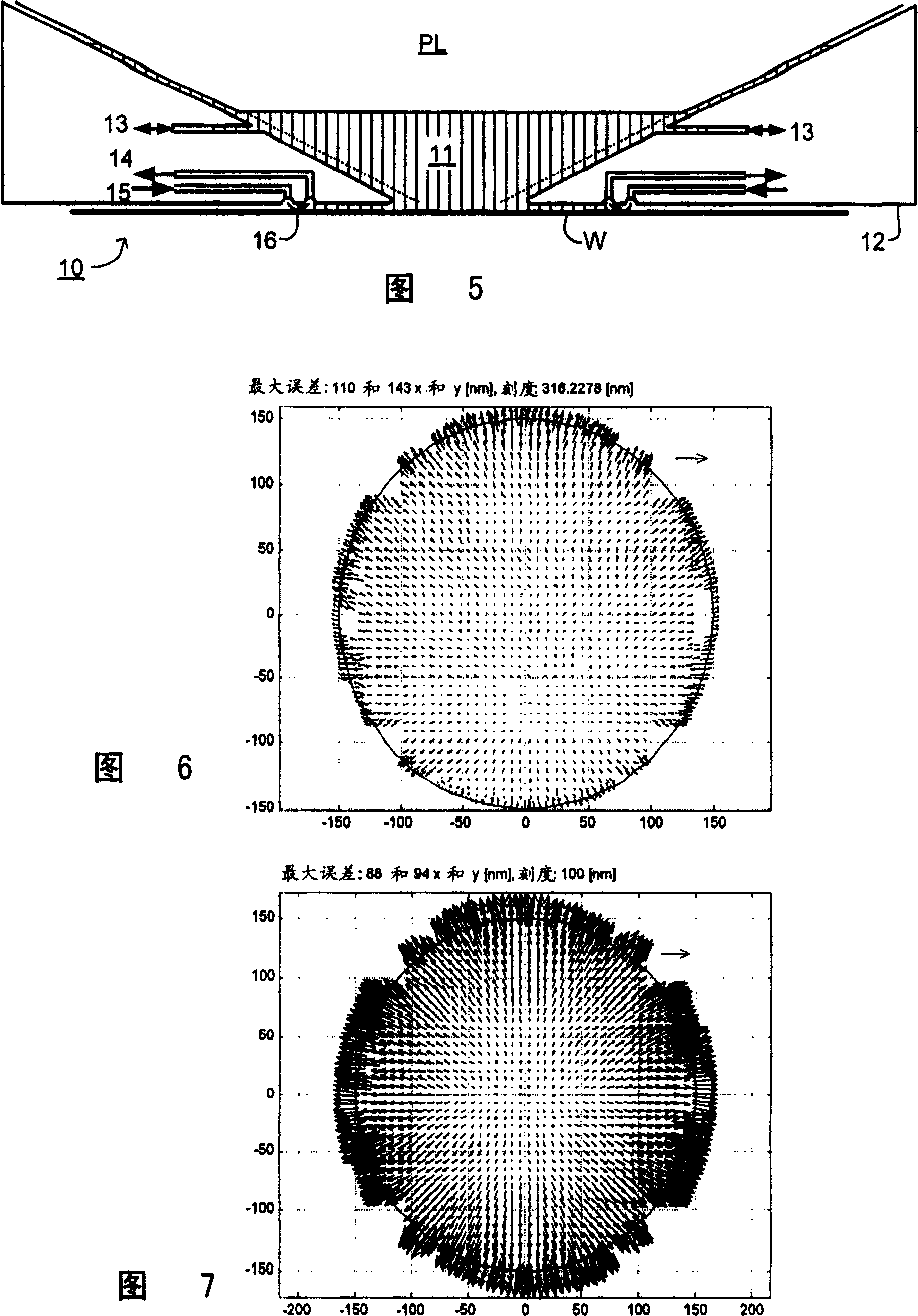
In calibration of overlay performance of an immersion lithographic apparatus, two sets of overlay data are obtained from exposures carried out using, for example, normal and reversed meanders. The two data sets can then be used to eliminate effects due to substrate cooling.

Description

Technical field [0001] The invention relates to a photolithography method. Background technique [0002] Lithographic equipment is a machine that applies a desired pattern on a substrate, usually on a target portion of the substrate. Lithographic equipment can be used, for example, in the manufacture of integrated circuits (ICs). For example, a patterning device alternatively referred to as a mask or a scribe line can be used to produce a circuit pattern to be formed on a single layer of an IC. This pattern can be transferred to a target portion (e.g., a portion that includes one or more dies) on a substrate (e.g., a silicon substrate). The pattern is typically transferred by imaging on a layer of radiation sensitive material (resist) provided on the substrate. Generally, a single substrate will contain a set of adjacent target portions that are successively patterned. Known lithographic equipment includes a so-called stepper, in which each target part is irradiated by exposing t...

Claims


Application Information

Patent Timeline
IPC IPC(8): G03F7/20H01L21/027
CPCG03F7/70341G03F7/7045G03F7/70633G03F7/70458G03F7/70516G03F7/706
Inventor K·J·J·M·扎尔A·J·德科特F·E·德琼K·古尔曼B·门希基科夫H·F·彭
Owner ASML NETHERLANDS BV
Why Eureka
Eureka Blog
Learn More