Filter and filter aggregate

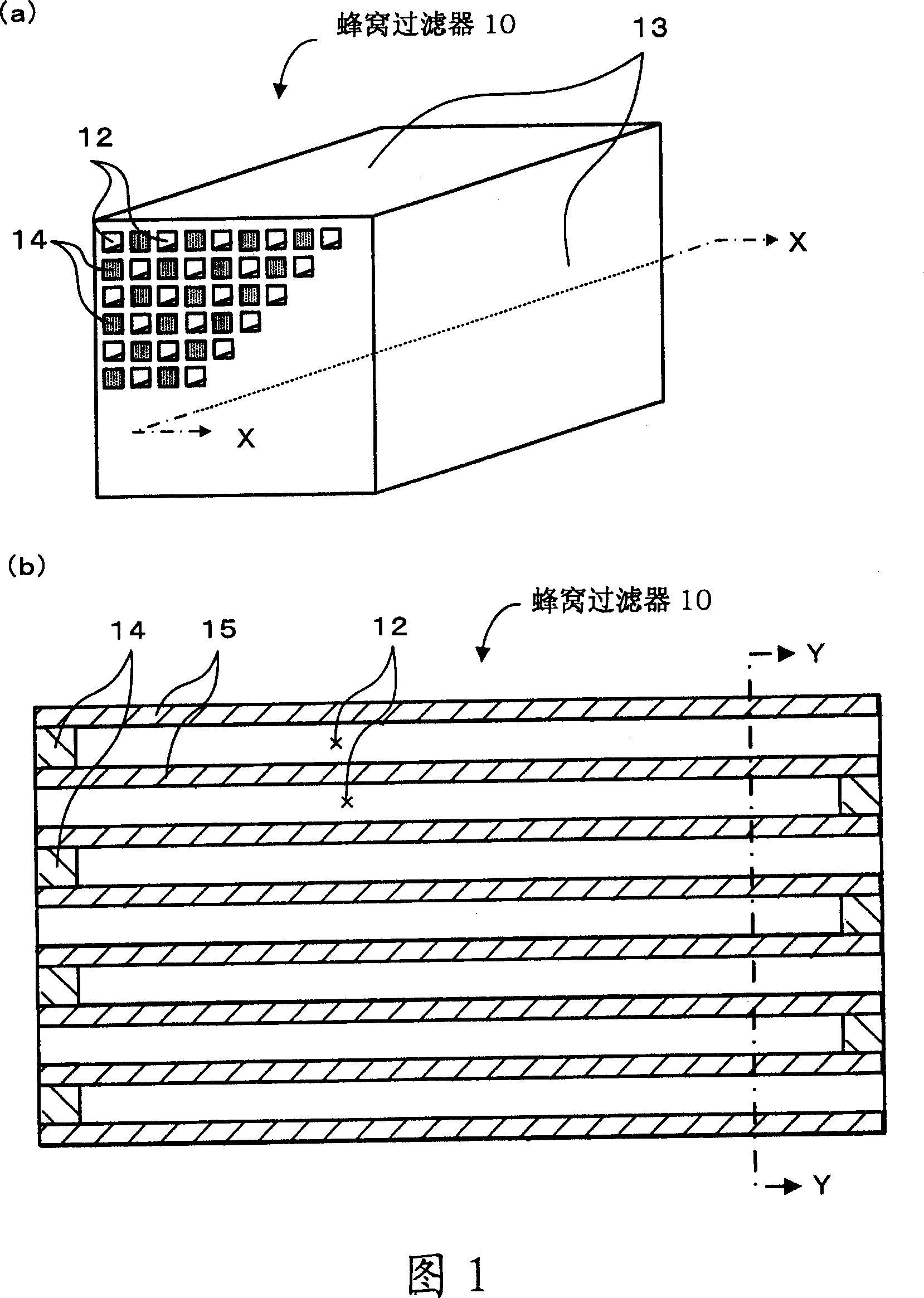
A technology of filters and aggregates, applied in membrane filters, filtration separation, dispersed particle filtration, etc., can solve the problems of not being able to sufficiently reduce pressure loss and capture particulate matter, opening ratio affects circulation, and pressure loss increases

Active Publication Date: 2007-03-07
IBIDEN CO LTD
View PDF1 Cites 7 Cited by
  • Summary
  • Abstract
  • Description
  • Claims
  • Application Information

AI Technical Summary

Problems solved by technology

[0003] However, in the filter described in this gazette, in the case of producing a filter with a large volume of large pores, increasing the wall thickness so as to satisfy P1×10≦T may result in an increase in pressure loss.
In addition, in the case of manufacturing a filter with a small pore size and a large volume of pores, reducing the wall thickness to satisfy (1 / P3)×1500≥T may result in a decrease in the capture efficiency of particulate matter.
In addition, the opening ratio and the like also affect the flow of gas. Therefore, only adjusting the wall thickness may not be able to sufficiently reduce the pressure loss and capture particulate matter.

Method used


Image

  • Filter and filter aggregate
  • Filter and filter aggregate
  • Filter and filter aggregate

Examples


experiment example 1

[0052] First, 6720 parts by weight of α-type silicon carbide powder (average particle diameter 22 μm) as coarse silicon carbide, 2880 parts by weight of α-type silicon carbide powder (average particle diameter 0.5 μm) as particulate silicon carbide, 980 parts by weight Acrylic resin particles (average particle size 20 μm) and 2970 parts by weight of water as a pore-forming agent are mixed, and 1050 parts by weight of methyl cellulose as an organic binder, 500 parts by weight of glycerol as a plasticizer , and 230 parts by weight of a lubricant (trade name unilube (UNILUBE); manufactured by NOF Corporation), were kneaded to obtain clay. Table 1 summarizes the raw materials of the honeycomb filter 10 in Experimental Example 1, the average particle size of each raw material, and the numerical values ​​of the added amount. In addition, Table 1 also collectively shows the contents related to Experimental Examples 2 to 34 described later. Next, the clay is extruded using an extrusi...

experiment example 2~34

[0058] Mix the raw materials according to the amount of addition shown in Table 1, and design the opening ratio C, wall thickness, and pore density shown in Table 2. In addition, use the same method as Experimental Example 1 to make experimental examples 2 to 34. Honeycomb filter 10.

[0059] [Measurement of Pore Diameter / Porosity]

[0060] The pore diameter / porosity measurement of Experimental Examples 1-34 was performed. As a measuring machine, an automatic porosity measuring instrument AutoPore III9405 manufactured by Shimadzu Corporation was used, and the measurement was performed by a mercury porosimetry in accordance with JIS-R1655. Specifically, the portion of the honeycomb filter 10 that does not include the plugged portion 14 is cut into a cube with a side of about 0.8 cm, ultrasonically cleaned with ion-exchanged water, dried, and measured using the above-mentioned measuring machine at a thickness of 0.1 μm to 360 μm. Measure within the measuring range. In the ran...


PUM

PropertyMeasurementUnit
Wall thicknessaaaaaaaaaa

Abstract

A filter and filter aggregate are provided. A honeycomb filter (10) which has a plurality of through holes (12) and, formed on the wall portion (15) between said through holes, a coated layer carrying a catalyst, wherein the filter (10) satisfies 2.5 * A / B + 52.5< = C <= 2.5 A / B + 60.2 (A <= 20, 0 < B <= 20) after the formation of the coated layer and the support of the catalyst, wherein A (%) represents the proportion of the pore volume of the pores having a pore diameter of 10 m or less relative to the total pore volume of the wall portion (15), B(%) represents the proportion of the pore volume of the pores having a pore diameter of 30 m or more relative to the total pore volume of the wall portion (15), and C (%) represents the proportion of opening of the plane intersecting with the above through holes (12). It is preferred that the filter (10) further satisfies 2.5 * A / B + 55.5 <= C, which results in further reduction of a pressure loss. It is also preferred that the filter (10) further satisfies C <= 2.5 A / B + 58.0, which results in further improvement of the efficiency of capturing particulate materials.

Description

technical field [0001] The present invention relates to a filter and filter assembly. Background technique [0002] Conventionally, as a filter, a filter in which the wall thickness between through-holes is improved in accordance with the pore distribution has been proposed. For example, in the filter described in Japanese Patent Application Laid-Open No. 2001-269522, if the ratio of the volume of pores with a pore diameter of 30 μm or more to the total pore volume is P1, and the wall thickness is T , when P1 is 10%, the wall thickness T is set to be 100 μm or more, and when P1 is 30%, the wall thickness T is set to be 300 μm or more, that is, P1×10≦T is satisfied. In addition, if the ratio of the volume of pores with a pore diameter of less than 3 μm to the total pore volume is P3, and the wall thickness is T, when P3 is 10%, the wall thickness T is 150 μm or less, and P3 is 30%. , set the wall thickness T to be 50 μm or less, that is, satisfy (1 / P3)×1500≥T. In this way,...

Claims


Application Information

Patent Timeline
IPC IPC(8): B01D39/20
CPCC04B35/584C04B2237/064B01D2046/2496B01D46/247B01D46/2466B01D2275/30C04B35/195C04B2111/0081C04B35/565B01J23/42C04B37/005C04B2235/5472C04B2111/00793B01D46/2459B01J35/04C04B2235/3826C04B2235/528C04B38/0009B01D46/2474C04B2237/365C04B2235/5436B01D2046/2437C04B2237/62C04B2235/425B01D46/2429C04B38/0019B01J37/0242Y10S55/30Y10S55/10B01D46/24492B01D46/2498B01D46/2484B01D46/2482B01D46/2478B01J35/56C04B38/0054C04B38/0074C04B38/068B01D39/20
Inventor 林正幸尾久和丈大平朗宏大野一茂
Owner IBIDEN CO LTD
Why Eureka
Try Eureka