Vacuum heat-insulating material and method for making same
A technology of vacuum heat insulation material and manufacturing method, which is applied in the direction of chemical instruments and methods, heat exchange equipment, household refrigeration equipment, etc., can solve the problems of large electricity and heat energy, increased environmental load, and large cost burden, so as to reduce costs, The effect of improving processing performance
- Summary
- Abstract
- Description
- Claims
- Application Information
AI Technical Summary
Problems solved by technology
Method used
Image
Examples
no. 1 example
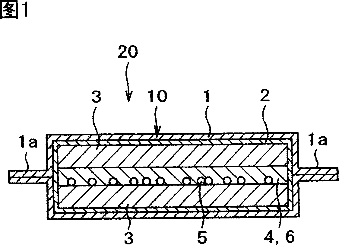
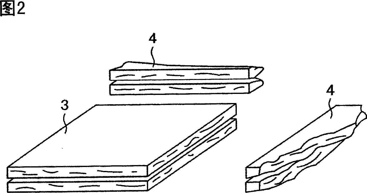
[0042] A vacuum insulation material and a manufacturing method thereof according to a first embodiment of the present invention will be described with reference to FIGS. 1 to 5 .
[0043] First, the structure of the vacuum heat insulating material 20 of the present embodiment will be described with reference to FIG. 1 . FIG. 1 is a cross-sectional view of a vacuum insulation material 20 according to a first embodiment of the present invention.
[0044] The structure of this vacuum heat insulating material 20 includes a core material 10 and an outer covering material 1 having gas barrier properties. The core material 10 is accommodated in the outer covering material 1 and decompressed, and the peripheral portion thereof is sealed by fusion bonding. The vacuum heat insulating material 20 is formed of a flat rectangular plate.
[0045]The structure of the core material 10 includes: a new material 3 composed of an inorganic fiber aggregate not containing a binder, a waste materi...
no. 2 example
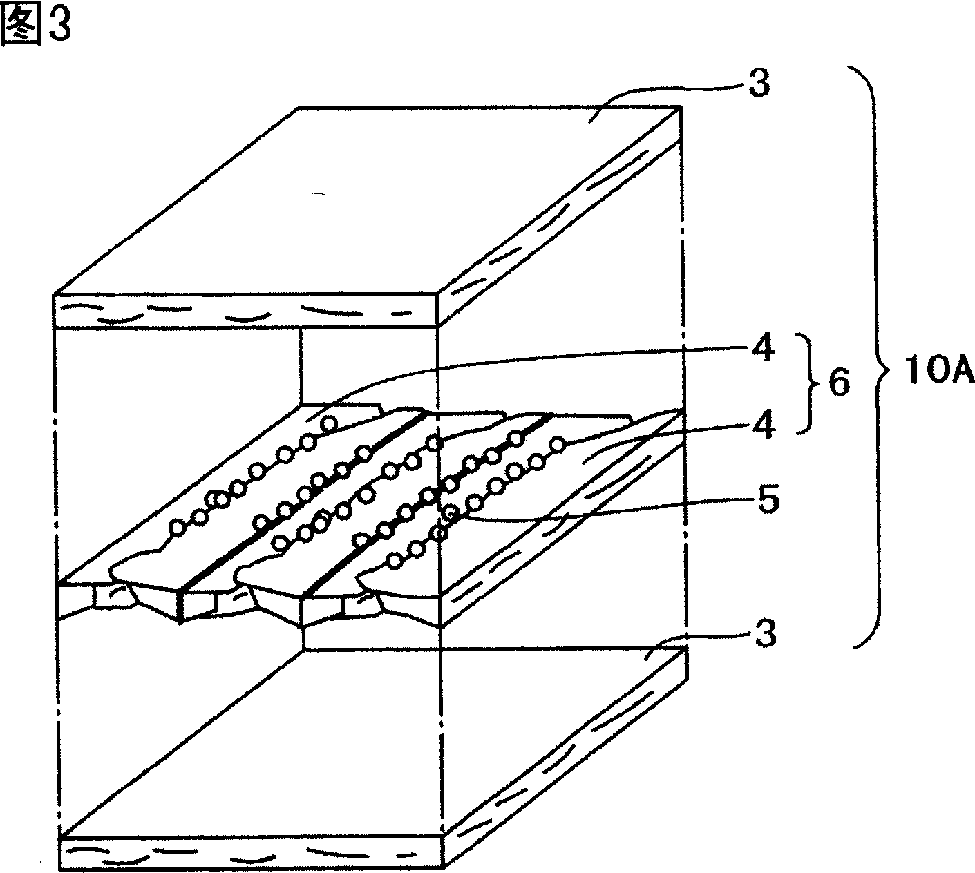
[0066] Next, a second embodiment of the present invention will be described with reference to FIG. 6 . Fig. 6 is a perspective view at the time of assembling the core material raw material 10A used in the vacuum heat insulating material 20 of the second embodiment of the present invention. The points of difference between the second embodiment and the first embodiment will be described below. For other aspects, since they are basically the same as the first embodiment, repeated descriptions will be omitted.
[0067] In the vacuum heat insulating material 20 of the second embodiment, waste materials 4 generated when cutting a binder-free glass wool laminate with an average fiber diameter of 4 μm into the size of a new material 3 are all used as core material raw materials. On 10A, the core material blank 10A made of 100% waste material is compressed and packaged with the inner cladding material 2 . In other words, the vacuum insulation material 20 is composed of three waste ma...
no. 3 example
[0070] Next, a third embodiment of the present invention will be described with reference to FIG. 8 . Fig. 8 is a cross-sectional view showing the combination of the core material blanks 10B used in the vacuum heat insulating material 20 according to the third embodiment of the present invention. The points of difference between the third embodiment and the first embodiment will be described below. For other aspects, since they are basically the same as the first embodiment, repeated descriptions will be omitted.
[0071] The vacuum heat insulating material 20 of the third embodiment uses a new material 3 composed of inorganic fiber aggregates not containing a binder and a core material composed of the waste material 4, and compresses and packs the core materials separately. Although the thermal conductivity of the vacuum insulation material 20 obtained in the third example is compared with that of the first example, when measured with the thermal conductivity measuring machin...
PUM
| Property | Measurement | Unit |
|---|---|---|
| density | aaaaa | aaaaa |
| thickness | aaaaa | aaaaa |
| density | aaaaa | aaaaa |
Abstract
Description
Claims
Application Information
 - R&D
- Intellectual Property
- Life Sciences
- Materials
- Tech Scout
- Unparalleled Data Quality
- Higher Quality Content
- 60% Fewer Hallucinations
Browse by: Latest US Patents, China's latest patents, Technical Efficacy Thesaurus, Application Domain, Technology Topic, Popular Technical Reports.
© 2025 PatSnap. All rights reserved.Legal|Privacy policy|Modern Slavery Act Transparency Statement|Sitemap|About US| Contact US: help@patsnap.com


