
Rocket solid propellant burning velocity testing system

A solid propellant and testing system technology, which is applied in fuel oil testing, material inspection products, etc., can solve the problems of low precision, difficulty in obtaining accurate test results, and low testing accuracy, so as to reduce labor intensity, expand the measurement range, and improve testing. The effect of precision

Inactive Publication Date: 2007-01-03
XIDIAN UNIV
View PDF0 Cites 29 Cited by
  • Summary
  • Abstract
  • Description
  • Claims
  • Application Information

AI Technical Summary

Problems solved by technology

Due to the narrow measurement range of the acoustic signal generated by propellant combustion, large errors in data processing methods, and low test accuracy, etc.
Especially for the drug strips whose burning rate is greater than 27mm / s and less than 4mm / s, it is difficult to obtain accurate test results, some formulations cannot obtain the burning rate pressure index and the test system has a low degree of automation
The valves that control the combustion chamber inlet and outlet, inlet and outlet, and pressure adjustment are all manual valves, with low control accuracy
The existing equipment uses an electric stopwatch for timing, which has a long measurement cycle and low precision, and the labor intensity of the measurement personnel is high
Signal acquisition uses image recorders, digital counters and other equipment to record acoustic emission signals, which not only has large errors, but also brings inconvenience to subsequent data statistics and processing
In the data processing method, the traditional data processing method adopts the single-point average calculation method in the calculation of the temperature sensitivity coefficient and the pressure index curve, which leads to a large error introduced in the calculation

Method used


Image

  • Rocket solid propellant burning velocity testing system
  • Rocket solid propellant burning velocity testing system
  • Rocket solid propellant burning velocity testing system

Examples


Embodiment Construction

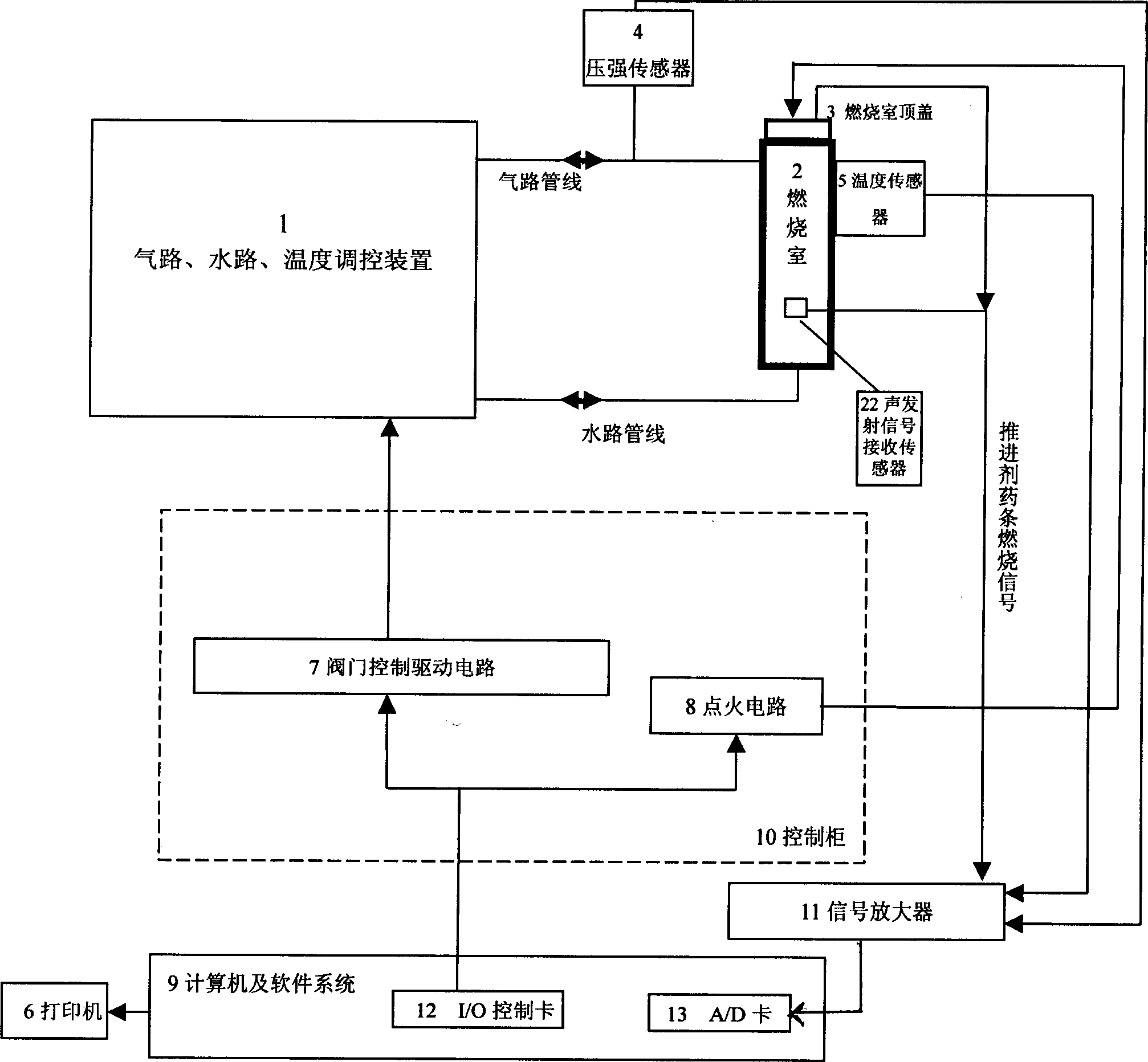
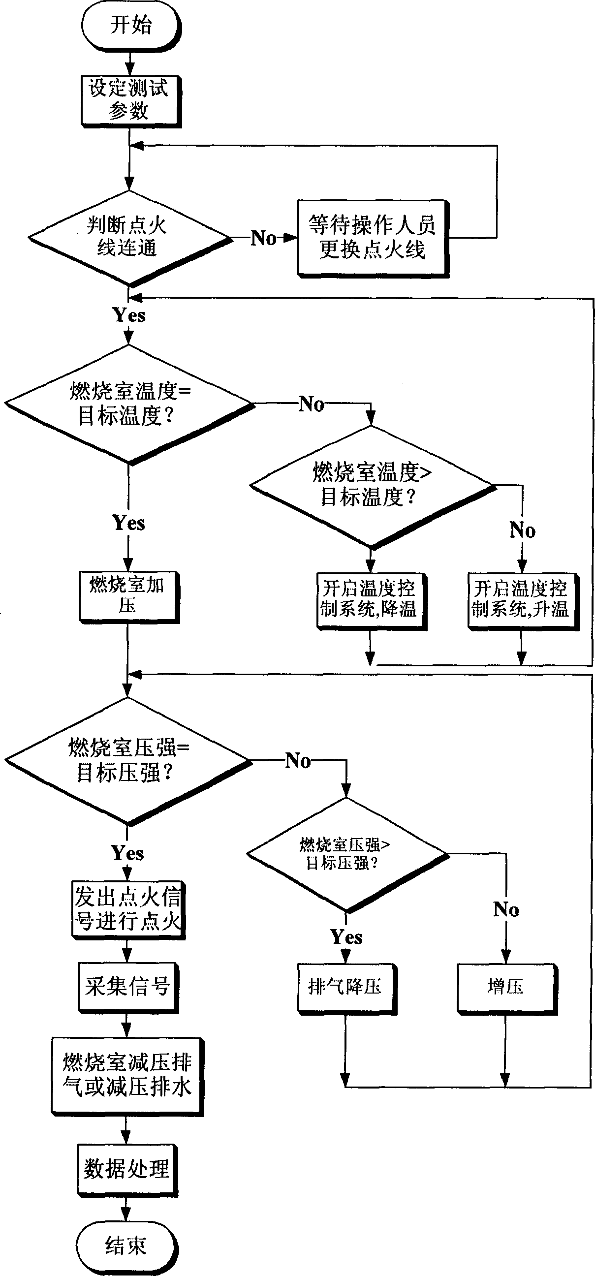
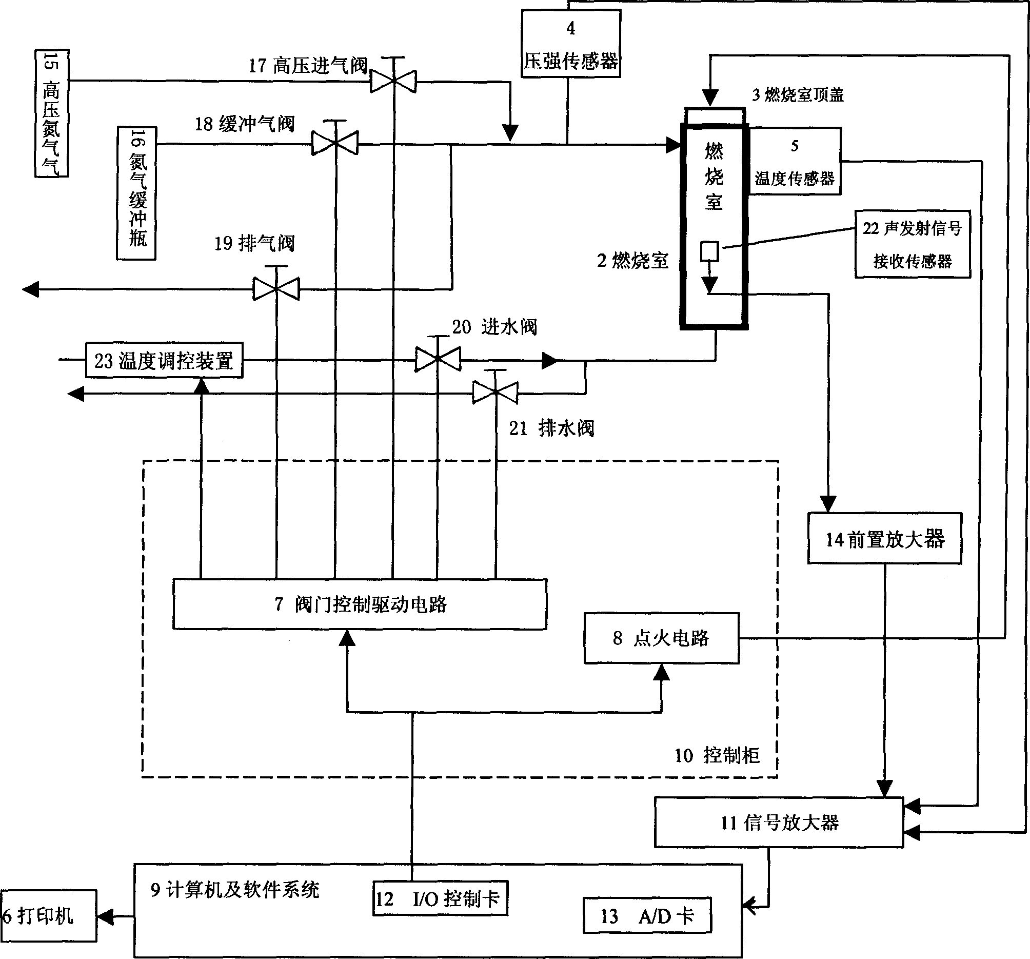
[0015] refer to figure 1 , which is a schematic diagram of the system structure of the present invention, the system is composed of a combustion chamber 2, a signal acquisition device, a gas circuit, a water circuit, a temperature control device 1 and a system control device. The combustion chamber 2 has an inlet / drainage port and an inlet / exhaust port, and the combustion chamber 2 is equipped with a combustion chamber top cover 3 on which copper electrodes are installed. Gas circuit, water circuit and temperature control device 1 have high-pressure nitrogen gas source, buffer nitrogen cylinder, high-pressure inlet valve, buffer gas valve, exhaust valve, water inlet valve, drain valve, temperature control device and corresponding air pipes and water pipes. The signal acquisition device includes a pressure sensor 4 , a temperature sensor 5 , an acoustic emission signal receiving sensor 22 , a copper electrode on the top cover of the combustion chamber 3 , a signal amplifier 11 ...


PUM


Abstract

A rocket solid propellant combustion speed test system relates to test equipment technology field. It enhances the test precision and test efficiency of the solid propellant combustion speed, achieves the management of the test date and data self-disposal to complete the automatization of the test process. It adopts the computer technology based on the existing technology. The system relates to firebox, signal collection equipment, gas way, waterway, temperature adjust equipment and designed system control equipment. The system control equipment relates to computer, control soft and control box made up of valve control drive circuit and ignition circuit. Signal collection equipment gets test signal from the firebox and magnifies it to carry to system control equipment. The computer deals with the data and sends control signal to the valve controlled by the valve control drive circuit and ignition circuit to switch on, interdict or ignite the solid propellant drug bar. It is mainly used for the rocket solid propellant combustion speed test.

Description

technical field [0001] The invention relates to the technical field of test instruments, in particular to a rocket solid propellant burning rate test system, which can be used for measuring the rocket solid propellant burning rate by underwater acoustic emission method and target line method. Background technique [0002] The current test method for the acoustic emission burning rate of rocket solid propellant in China began in the 1980s, while the target line test method for rocket solid propellant was earlier. For details, see "Research on High-Pressure Burning Velocity Acoustic Emission Test Technology" published by Xu Zairong in "Solid Rocket Technology" in 1997 and "The Burning Velocity test". Due to the narrow measurement range of the acoustic signal produced by propellant combustion, large errors in data processing methods, and low test accuracy, etc. In particular, it is difficult to obtain accurate test results for medicinal strips whose burning rate is greater th...

Claims


Application Information

Patent Timeline
IPC IPC(8): G01N33/22
Inventor 刘科祥李楠赵吉成
Owner XIDIAN UNIV
Learn More