Orthodontic arch filament forming method and apparatus
A technology of orthodontic arch wire and forming method, which is applied in the direction of furnace type, heat treatment equipment, furnace, etc., can solve the problems of difficult heating temperature, inability to grasp the heat treatment process of arch wire, and inability to automatically control the temperature change of arch wire in real time
- Summary
- Abstract
- Description
- Claims
- Application Information
AI Technical Summary
Problems solved by technology
Method used
Image
Examples
specific Embodiment approach 1
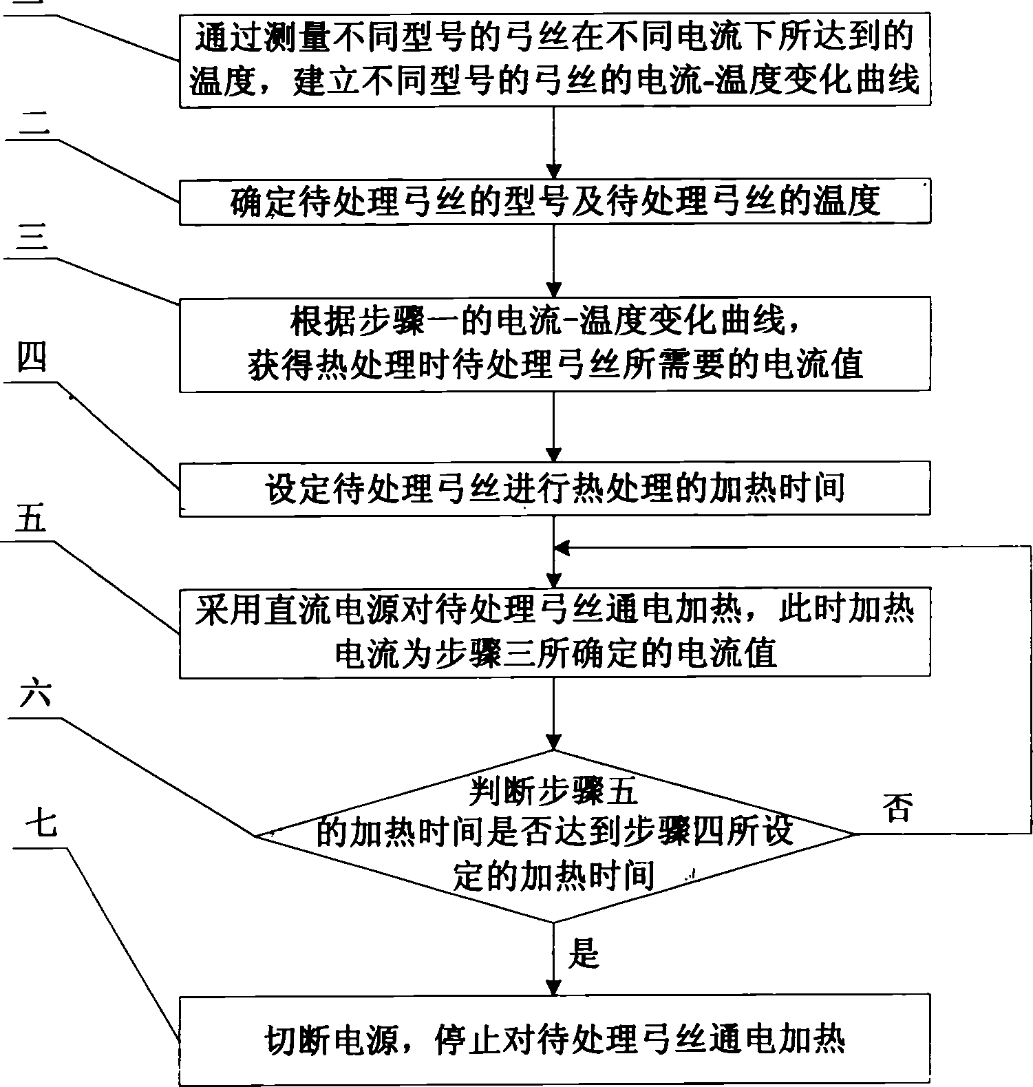
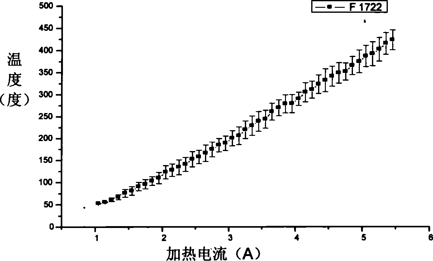
[0019] Specific implementation mode one: see figure 1 , the method for forming an orthodontic arch wire according to the specific embodiment is carried out according to the following steps: Step 1. The K-type thermocouple wire connected to the arch wire by spot welding is used to measure the processing temperature of the arch wire to be processed. The temperature reached by the arch wire under different currents, and the current-temperature curves of different types of arch wires are established, for example image 3 The current-temperature change curve of the nickel-titanium arch wire whose model is F1722 is shown; step 2, determine the model of the arch wire to be processed and the temperature of the arch wire to be processed; step 3, according to the current-temperature change curve obtained in step 1, Obtain the current value required by the archwire to be treated during heat treatment; Step 4, set the heating time for the archwire to be treated; Step 5, use a DC power sup...
specific Embodiment approach 2
[0020] Specific implementation mode two: see figure 1 The difference between this specific embodiment and specific embodiment 1 is that in step 1, during the measurement process, the heating time for each current value to the nickel-titanium arch wire is 7 seconds. Other steps are the same as in the first embodiment.
specific Embodiment approach 3
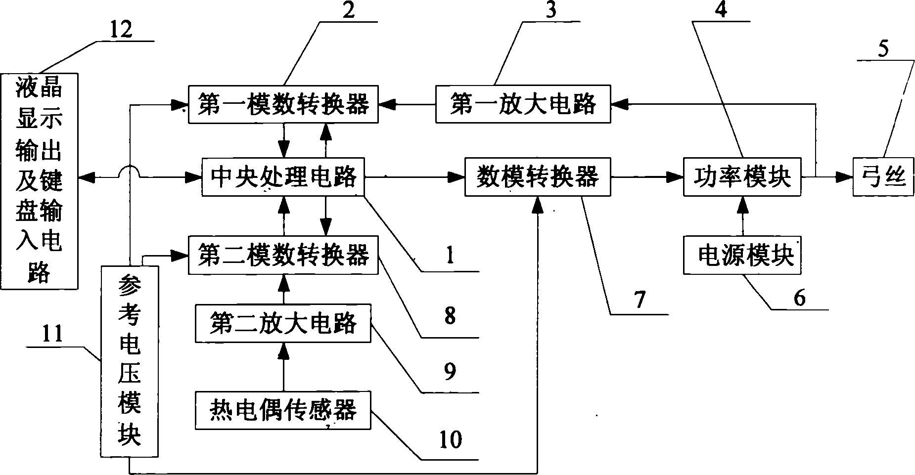
[0021] Specific implementation mode three: see figure 2 The orthodontic archwire forming device according to this specific embodiment consists of a central processing circuit 1, a digital Analog converter 7, power module 4, power supply module 6, first analog-to-digital converter 2 and first amplifying circuit 3 are composed; the current control signal output end of central processing circuit 1 is connected to the input end of digital-to-analog converter 7, digital-to-analog The output end of the converter 7 is connected to the power control end of the power module 4, the power module 6 provides a constant DC voltage for the power module 4, the constant current output by the power module 4 is supplied to the arch wire 5 to be processed, and the constant current output by the power module 4 is The feedback signal is amplified by the first amplifying circuit 3 and input to the input end of the first analog-to-digital converter 2, and the output end of the first analog-to-digita...
PUM
 Abstract
Description
Claims
Application Information
 - Generate Ideas
- Intellectual Property
- Life Sciences
- Materials
- Tech Scout
- Unparalleled Data Quality
- Higher Quality Content
- 60% Fewer Hallucinations
Browse by: Latest US Patents, China's latest patents, Technical Efficacy Thesaurus, Application Domain, Technology Topic, Popular Technical Reports.
© 2025 PatSnap. All rights reserved.Legal|Privacy policy|Modern Slavery Act Transparency Statement|Sitemap|About US| Contact US: help@patsnap.com


