Loose sheath type wire handle

A holding part, loose-sleeve technology, applied in the direction of maintaining the distance between parallel conductors, mechanical vibration damping devices, etc., can solve the problems of increased projected cross-sectional area, increased wind pressure load, complex structure, etc., and achieves improved aging characteristics. Effect

Inactive Publication Date: 2006-12-27
FURUKAWA ELECTRIC POWER SYST
View PDF3 Cites 3 Cited by
  • Summary
  • Abstract
  • Description
  • Claims
  • Application Information

AI Technical Summary

Problems solved by technology

As a result, the maximum amount of slack is not uniform in each unit conductor of the multi-core wire, which may give people a sense of insecurity in appearance, or increase the wind pressure load due to the increase in the projected wind-receiving area of ​​the multi-core wire.
[0011] In the loose sleeve bushing of Patent Document 2, for example, in a 4-core electric wire, observe the line direction, and grasp the upper and lower unit conductors on either side of the left and right as a loose sleeve Therefore, if the grip on the loose sleeve side is heavier than the grip on the fixed side, the influence of its poor quality makes the unit conductor not horizontal and tends to tilt to either side. Therefore, the multi-core conductor is easy to be damaged. Disadvantages such as twisting in strong winds, increase in projected cross-sectional area viewed from the horizontal direction, and increase in wind pressure load
In addition, as mentioned above, there are problems such as deterioration of corona characteristics due to twisting and inclination of multi-core conductors.
Therefore, it is necessary to install a balance ring or the like on the side of the grip part on either side, so that the balance ring is located between the loose grip grip part and the fixed grip part, and is used to balance the torque of the loose grip grip part and the fixed grip part, thereby increasing the Free parts, there are problems with safety measures such as falling during construction, and it consumes man-hours and is not economical
Furthermore, there are problems such as the large size of the grip part of the loose sleeve, its complicated structure, more assembly parts, and higher cost.

Method used


Image

  • Loose sheath type wire handle
  • Loose sheath type wire handle
  • Loose sheath type wire handle

Examples


Embodiment Construction

[0036] An embodiment of the loose sleeve type electric wire holding part of the present invention will be described in detail below with reference to the accompanying drawings.

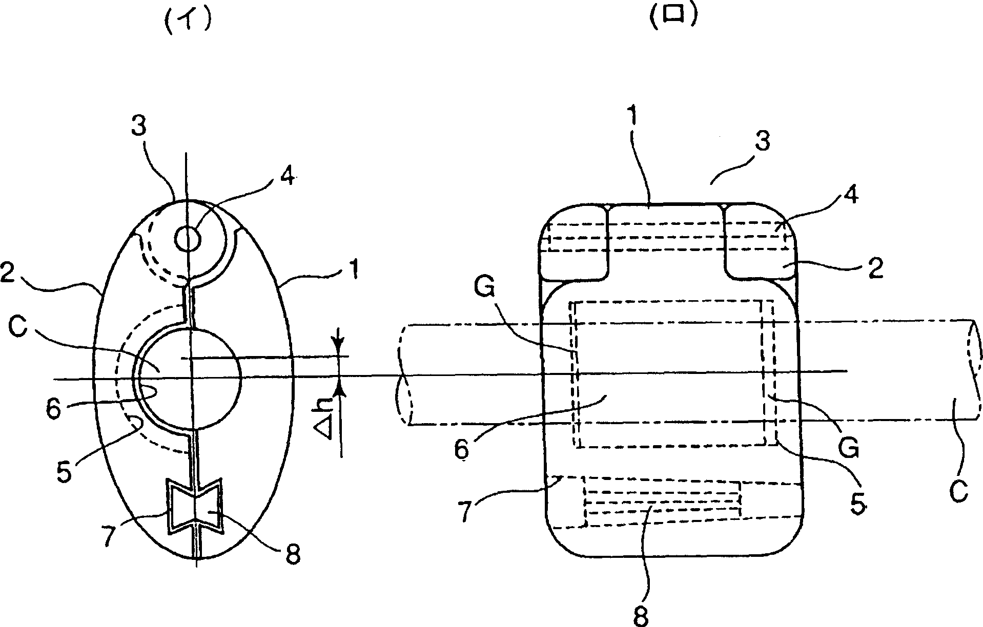
[0037] figure 1 It is a front view (□) and a side view (□) of a fixed ring binder which is a constituent part of the loose sleeve grip part of the present invention. exist figure 1 Among them, a hinge mechanism 3 is provided on one end of the fixed ring clamps 1 and 2, which can be freely opened and closed with the pin 4 as the axis. On one side 2 of the fixed ring binder, a receiving groove 5 for installing a resilient rubber-like elastic body ring 6 is formed. In addition, gaps (G) that are slightly longer than the length of the rubber-like elastic body ring 6 are provided on both sides in the longitudinal direction of the receiving groove 5 . The reason for this is that the coefficient of volume expansion of rubber or the like is one digit larger than that of aluminum or the like, and when the t...


PUM

PropertyMeasurementUnit
Thicknessaaaaaaaaaa

Abstract

The present invention provides one kind of sleeve type wire holder with less parts, simple and compact structure and low manufacture cost. Structurally, the sleeve type wire holder includes a ring clamp fixed to the wire with one hinged end for easy opening and closing, a semi-cylindrical elastic rubber ring set on the wire, a conic wedge inserted into one drum-shaped slot to fasten the rubber ring to the wire, and a block to limit the swinging range of the ring clamp around the wire.

Description

technical field [0001] The present invention relates to a loose-sleeve type electric wire gripping part, and relates to a structure of a loose-sleeve type electric wire gripping part which can be configured by attaching a so-called loose-sleeve bushing to a multi-core conductor to form a giyaropping type multi-core electric wire or the like. Background technique [0002] The ice and snow on the conductor of the single-core wire develops into a tube-shaped snow cover while sliding and rotating along the twisted groove in the length direction on the peripheral surface of the stranded conductor. If the conductor is also rotated by the tube-shaped snow cover The bottom is twisted (twisted) and rotated, which encourages the rotation of the tubular snow cover, making it develop into a larger tubular snow cover. [0003] However, since the conductors (unit conductors (prime conductors)) of the multi-core electric wire are connected to each other by bushings installed at predetermin...

Claims


Application Information

Patent Timeline
IPC IPC(8): H02G7/14H02G7/12
Inventor 宗像武男武田浩三井上充男中野纯加藤淳三洋明
Owner FURUKAWA ELECTRIC POWER SYST
Why Eureka
Try Eureka