In-situ concrete plate

A cast-in-place concrete slab and cast-in-place technology, applied in the field of cast-in-place concrete slabs, can solve problems such as displacement or dislocation, affecting the overall quality and mechanical performance of cast-in-place concrete slabs, and increasing construction difficulty

Inactive Publication Date: 2006-12-27
邱则有
View PDF1 Cites 1 Cited by
  • Summary
  • Abstract
  • Description
  • Claims
  • Application Information

AI Technical Summary

Problems solved by technology

However, in the construction of this type of cast-in-place concrete slab, the arrangement and positioning between each other is inconvenient, and displacement or dislocation is easy to occur, and the thickness of the cast-in-place concrete ribs between the formwork members is inconsistent and the cast-in-place concrete on the formwork members The thickness of the upper plate is inconsistent, which affects the overall quality and mechanical performance of the cast-in-place concrete slab, and increases the difficulty of construction. Therefore, it is urgently needed to develop a new type of cast-in-place concrete slab.

Method used


Image

  • In-situ concrete plate
  • In-situ concrete plate
  • In-situ concrete plate

Examples


Embodiment Construction

[0073] The present invention will be further described below in conjunction with the accompanying drawings and embodiments.

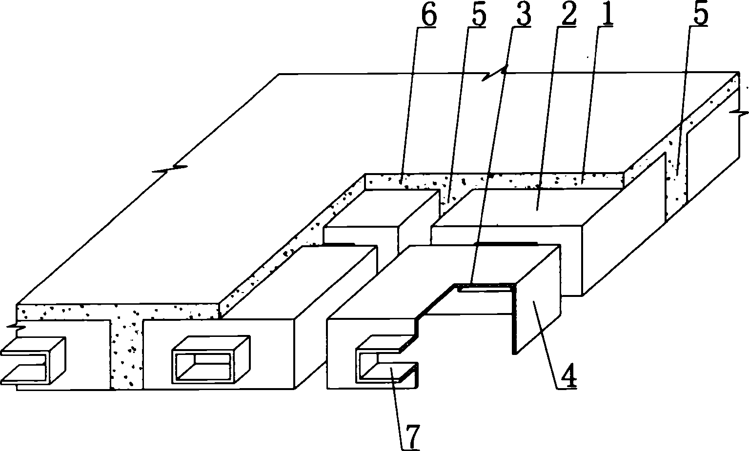
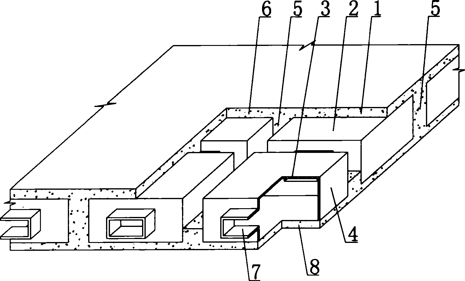
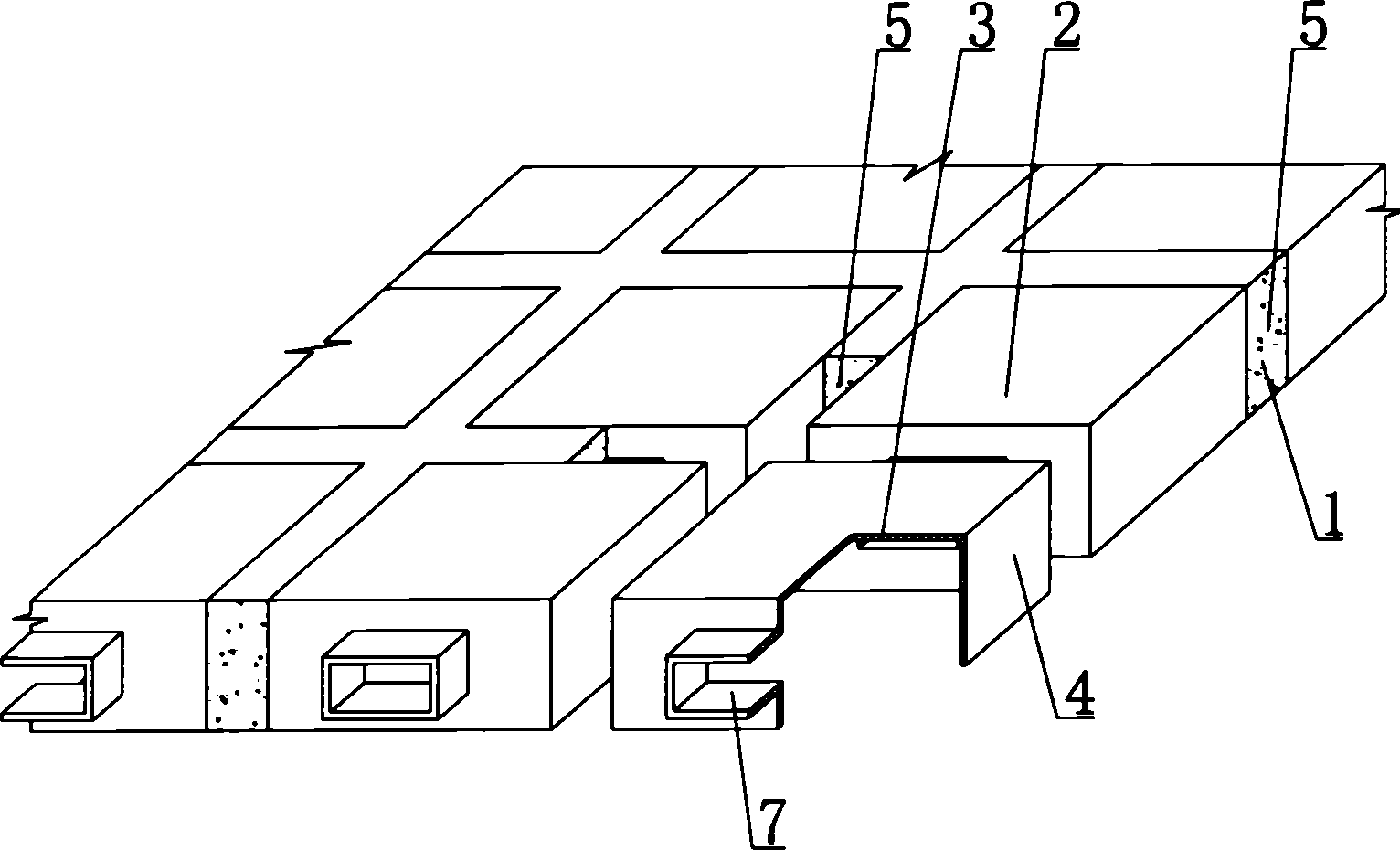
[0074] As shown in the accompanying drawings, the present invention comprises reinforced concrete 1, formwork member 2, formwork member 2 includes an upper plate 3, surrounding side walls 4, the upper plate 3, surrounding side walls 4 form an open basin-shaped member, and the formwork The surrounding side walls 4 of the shell member 2 are cast-in-place reinforced concrete ribs 5 formed by reinforced concrete 1, and the upper plate 3 of the formwork member 2 is a cast-in-place reinforced concrete laminated layer 6 formed by reinforced concrete 1, and Connected with the cast-in-place reinforced concrete ribs 5, the reinforced concrete 1 and the formwork member 2 are stacked together to form a whole, and the feature is that at least one connecting piece 7 is arranged on the basin-shaped member 2. In each drawing, 1 is reinforced concrete, 2 is formwork mem...


PUM


Abstract

Disclosed is a cast-in-situ concrete slab, which comprises a reinforced-bar concrete (1) and shuttering members (2), the shuttering members (2) comprise an upper board (3) and peripheral side panels (4), the upper board (3) and the peripheral side panels (4) encloses an open basin shape component, cast-in-situ reinforced bar concrete ribs (5) formed by the reinforced-bar concrete (1) are disposed between the peripheral side walls (4) of the shuttering members (2), cast-in-situ reinforced bar concrete overlapping layers formed by the reinforced-bar concrete (1) are disposed above the upper board (3) of the shuttering members (2), and is connected to the cast-in-situ reinforced bar concrete ribs (5), the reinforced-bar concrete (1) and the shuttering members (2) are superposed into an integrity, characterized in that a connecting member is arranged in the cavity of the basin form component, the invention can be applied to cast-in-situ reinforced concrete or prestressed reinforcement concrete's hollow storied-building roofings, house roofings, walls, foundation bedplates and hollow bridges, especially for hollow flat slabs.

Description

(1) Technical field [0001] The invention relates to a cast-in-place concrete board. (2) Background technology [0002] At present, most of the buildings with brick-concrete structure and frame structure use prefabricated hollow-core slabs as floor slabs. This kind of floor slab has the advantages of fast construction speed and low cost, but because there is no firm connection between two adjacent prefabricated hollow-core slabs , Only cement mortar is used to fill the gaps, so not only the integrity is poor, which is not conducive to earthquake resistance, but also cracks and water seepage often occur, causing great inconvenience and psychological pressure to the residents. In order to solve the above problems, many buildings have adopted the method of cast-in-place concrete slabs (hollow, solid). Although the cast-in-place concrete slab solves the problems of earthquake resistance and cracking, a large number of templates are used during construction, which not only increa...

Claims


Application Information

Patent Timeline
Patent Type & Authority Applications(China)
IPC IPC(8): E04B1/16E04B5/36E04B5/48E04C5/00E04G15/06
Inventor 邱则有
Owner 邱则有
Why Eureka
Try Eureka