Eureka AIR delivers breakthrough ideas for toughest innovation challenges, trusted by R&D personnel around the world.

Two-stage and multi-stage type-II absorption heat transformer

An absorption heat pump and new process technology, applied in the field of low-temperature waste heat utilization and energy-saving equipment, can solve the problems of increasing heat transfer links, increasing equipment complexity, and increasing energy consumption

Inactive Publication Date: 2006-12-13
李华玉
View PDF0 Cites 12 Cited by
  • Summary
  • Abstract
  • Description
  • Claims
  • Application Information

AI Technical Summary

Problems solved by technology

[0004] The traditional two-stage and multi-stage second-type absorption heat pump device is composed of an evaporator, a generator, an absorber and each intermediate absorber and each corresponding intermediate evaporator (including the intermediate connecting the corresponding absorber and the evaporator. Heat transfer loop), necessary circulation pump and other main components, the number of stages increases, the complexity of equipment increases, and the corresponding control system also increases; moreover, the heat produced by the intermediate absorber is transferred to the corresponding intermediate loop through the corresponding intermediate loop. The intermediate evaporator increases the heat transfer link
These aspects have led to the following deficiencies in the two-stage and multi-stage second-class absorption heat pumps of the traditional process structure: ① The existence of intermediate heat transfer links directly affects the increase of the heat supply temperature of the heat pump, or provides a certain amount of heat to the outside. Under the heating temperature, the requirement for the waste heat temperature is increased; or the temperature of the cooling medium is required to be lower
②Complicated equipment, many consumables, difficult manufacturing and high cost
③There are many moving parts, and the energy consumption increases, which affects the energy saving benefit
④The control system of the device is complicated, which increases the composition of the control system and increases the manufacturing cost
[0005] The existence of the above problems has greatly affected the popularization and application of this technology from the two aspects of heating temperature and equipment cost

Method used


Image

  • Two-stage and multi-stage type-II absorption heat transformer
  • Two-stage and multi-stage type-II absorption heat transformer
  • Two-stage and multi-stage type-II absorption heat transformer

Examples


Embodiment Construction

[0015] The present invention will be described in detail below in conjunction with the accompanying drawings and embodiments.

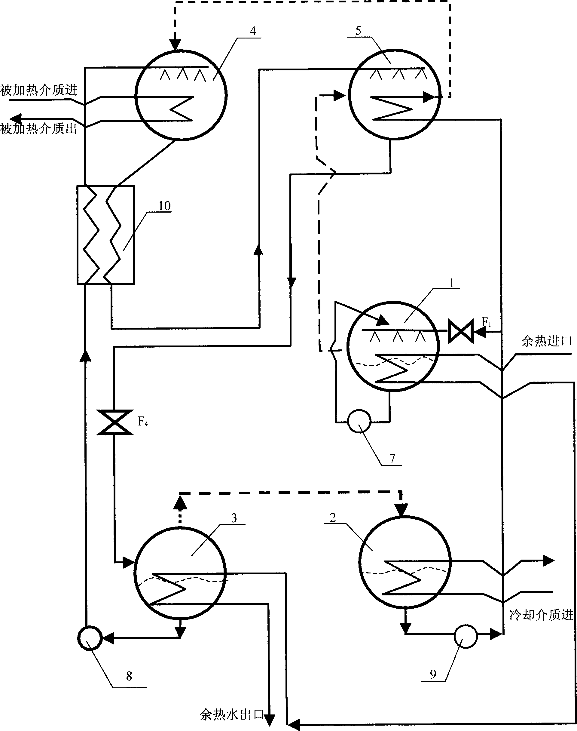
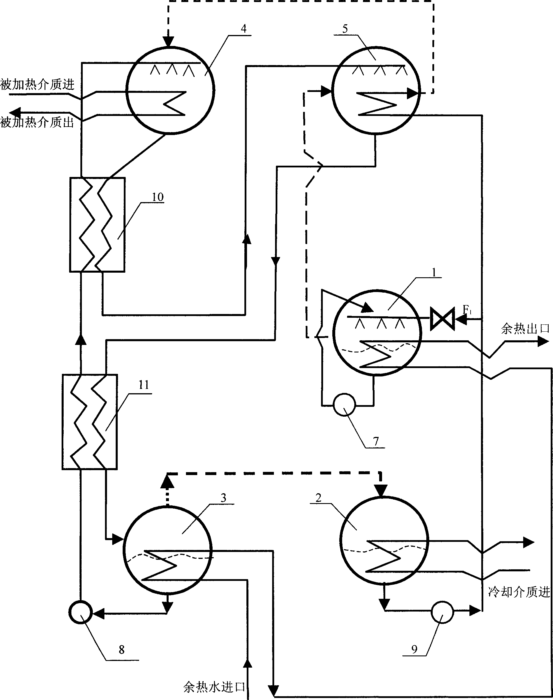
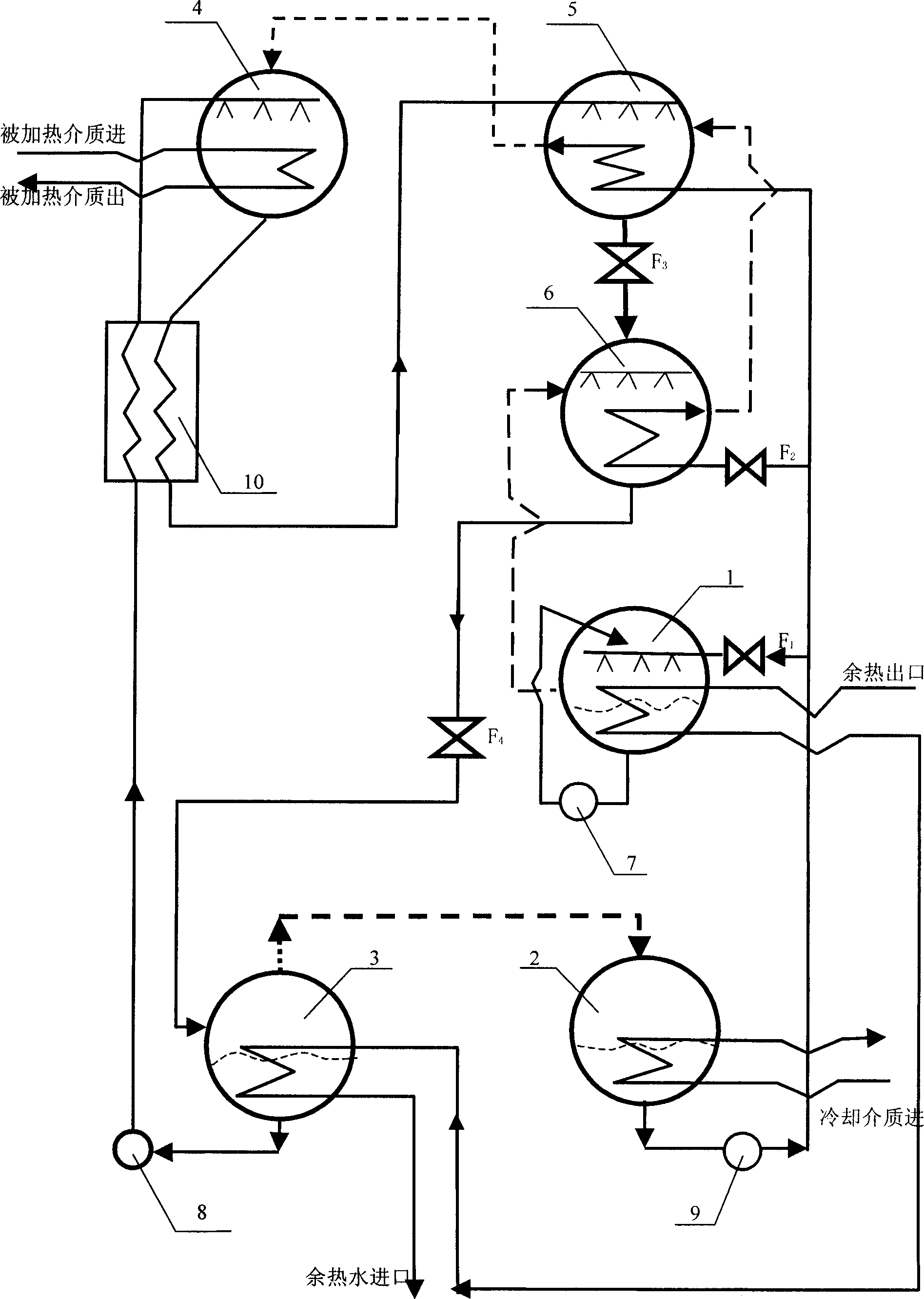
[0016] In the two-stage second type absorption heat pump, the purpose of the present invention is achieved like this, 1. structurally, this heat pump is mainly made up of evaporator 1, condenser 2, generator 3, absorber 4 and absorption-evaporator 5, There is no longer an intermediate absorber and its corresponding intermediate evaporator that rely on the intermediate circuit for heat exchange; ②The waste heat fluid either enters the evaporator 1 first, then enters the generator 3, or enters the generator 3 first, and then enters the evaporation The device 1 is the same as the traditional structure and process; ③The solution from the absorber 4 enters the absorption-evaporator 5, and inside it, the solution absorbs the refrigerant vapor from the evaporator, and this process is carried out outside the heat exchange tube bundle; The heated refrigerant m...


PUM


Abstract

The invention relates to a two-stage and multistage adsorption heat pump, belonging to the waste heat utilization technique. Wherein, it combines the middle absorbers with the middle vaporizer, to form adsorption-vaporization device; inside the adsorption-vaporization device, solution absorbs the steam of coolant from the vaporizer or superior (low-pressure) adsorption-vaporization device that processed outside the heat exchange tube; and the heated coolant from the coolant hydraulic pump flows the tube, the heat generated by using solution to absorb the steam of coolant is directly used to heat and gasify the coolant. Compared with present structure, the invention reduces the number of middle absorber and vaporizer, to make the number of adsorption-vaporization device lower 1 than the stage number, based on four basic elements that vaporizer, condenser, generator and absorber. The invention simplifies the process, improve the thermal parameter, and improve the temperature.

Description

Technical field: [0001] The invention belongs to the field of low-temperature waste heat utilization energy-saving equipment and technology. Background technique: [0002] Using absorption heat pump technology for waste heat utilization is an effective means, which has relatively good energy saving, environmental protection and economic benefits. In the case of relatively abundant waste heat resources, the adoption of the second type of absorption heat pump technology can bring better energy-saving benefits. For the second type of absorption heat pump, there are single-stage, two-stage and multi-stage (more than two stages). As the number of stages increases, the heating temperature increases, but the equipment is becoming more and more complicated and difficult to manufacture. and cost also increased. [0003] In the occasions where waste heat resources are abundant, if the waste heat temperature is relatively low, or the user’s heat consumption temperature requirement is...

Claims


Application Information

Patent Timeline
IPC IPC(8): F25B30/04
Inventor 李华玉
Owner 李华玉
Why Eureka
Eureka Blog
Learn More