
Optical buffer with adjustable delay time and output wavelength

An optical buffer and delay time technology, which is applied to the coupling of optical waveguides, wavelength division multiplexing systems, selection devices for multiplexing systems, etc. Fully meet the performance requirements of optical router delay time and output wavelength adjustable performance, achieve good signal-to-noise ratio, improve anti-noise capability, and facilitate adjustment.

Inactive Publication Date: 2006-11-22
SHANGHAI JIAO TONG UNIV
View PDF1 Cites 8 Cited by
  • Summary
  • Abstract
  • Description
  • Claims
  • Application Information

AI Technical Summary

Problems solved by technology

[0004] After searching the documents of the prior art, it is found that in the U.S. patent, the patent number is US6900920B2, and the patent name is: "Variable semiconductor all-optical buffer using slow lightbased on electromagnetically induced transparency" (slow light based on the principle of electric field transparency to realize variable In the semiconductor all-optical buffer), Connie J. et al. proposed a slow light based on the principle of electric field transparency to realize a variable semiconductor all-optical buffer. This kind of optical buffer is suitable for the fine adjustment of optical buffer, and generally only Reaching the order of several bits, it is obviously incompetent for the long delay time required by some routing systems; and in "Electrically In "tunabledelay line using an optical single-side-band modulator" (optical single-sideband modulator realizes electronically controlled adjustable delay line), Tetsuya Kawanishi et al. use the principle of signal wavelength reflection in the Bragg grating frequency band, and propose a wavelength conversion based The optical buffer structure is simpler than the optical buffer composed of delay lines, and can realize data packet buffering and wavelength conversion functions, but it is difficult to adjust the delay time, and the output wavelength is fixed. Systems with wavelength conversion are not suitable
[0005] The above results show that the current existing solutions cannot fully meet the performance requirements of optical routers for the adjustable delay time and output wavelength of optical data packets, especially in the optical packet switching technology based on the store-and-forward mechanism. The delay time is adjustable, and the adjustable output wavelength is required in the WDM high-speed transmission system

Method used


Image

  • Optical buffer with adjustable delay time and output wavelength
  • Optical buffer with adjustable delay time and output wavelength
  • Optical buffer with adjustable delay time and output wavelength

Examples


Embodiment Construction

[0024] The technical solutions of the present invention will be further described below in conjunction with the accompanying drawings and embodiments.

[0025] In this embodiment, an optical buffer with adjustable delay time and output wavelength can realize any adjustable delay time for input data packets, and the output wavelength is also adjustable.

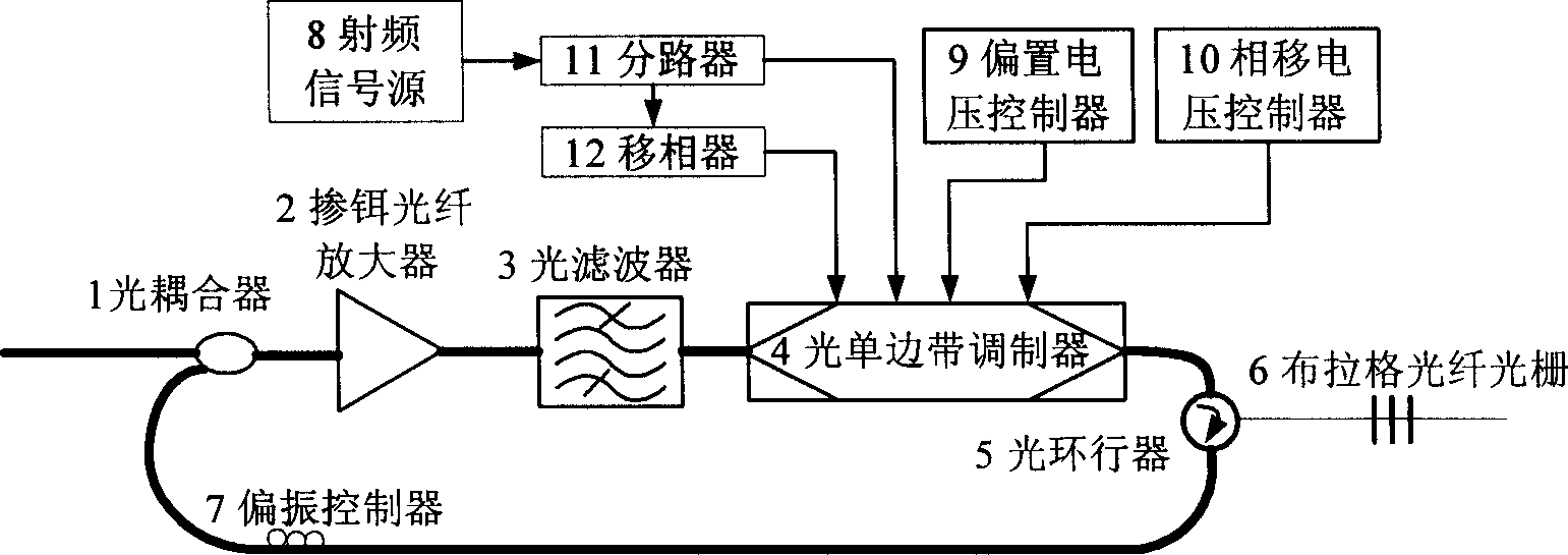
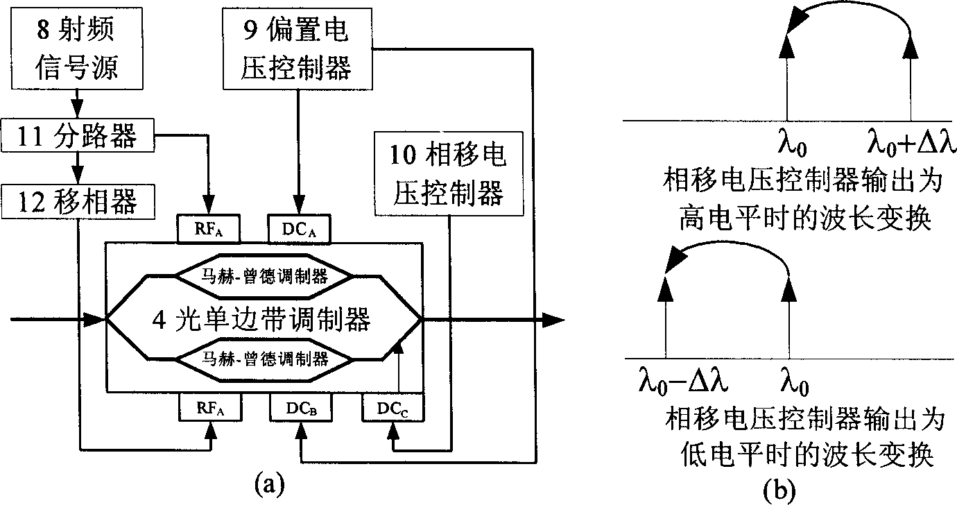
[0026] A structural diagram of an optical buffer with adjustable delay time and output wavelength is shown in figure 1As shown, it includes 2×1 optical coupler 1, erbium-doped fiber amplifier 2, optical filter 3, single sideband modulator 4, circulator 5, fiber Bragg grating 6, polarization controller 7, radio frequency signal source 8, polarization A voltage controller 9, a phase shift voltage controller 10, a splitter 11 and a phase shifter 12 are provided. The 2×1 optical coupler 1 can couple the input optical signal into the optical buffer, and can also couple the input optical signal to the optical buffer by the fiber Bra...


PUM


Abstract

The invention discloses a delay time and export wavelengh adjustable optical buffer memory, which is characterized by the following: one of two input of the 2 X1 optical coupler is input port of optical buffer memory which connect outside; another port connects polarization controller; output of 2X1 optical coupler connects erbium-doped fiber amplifier; output of erbium-doped fiber amplifier connects input of optical electric filter; the output of optical electric filter links up optical single sideband demodulator; the radiofrequency signal source, bias voltage controller, phase voltage controller connect to control port of optical single selvage modulator; the output of optical single selvage modulator connects input of circulator; the output of circulator links up Bragg's fibre-optical pattern; the loopback port of circulator connects polarization controller. The invention adjusts the dalay time and export wavelengh, which reduces the power damage.

Description

technical field [0001] The invention relates to an optical buffer in the technical field of optical communication, in particular to an optical buffer with adjustable delay time and output wavelength. technical background [0002] In recent years, with the rapid development of the Internet, the data business has shown a rapid growth trend, which requires the network to have enough bandwidth to use, and requires the network nodes to have a high enough data throughput, and these are the applications of packet switching technology in WDM networks advantage. WDM optical transport network has excellent transmission performance and provides sufficient bandwidth for information transmission; packet switching technology is the best choice for fast data exchange. The optical packet switching technology organically combines the two, can greatly expand the existing network bandwidth, and maximize the line utilization rate, which is considered to be one of the development trends of the ...

Claims


Application Information

Patent Timeline
Patent Type & Authority Applications(China)
IPC IPC(8): H04J14/02G02B6/26H04Q11/00
Inventor 徐新余苏翼凯
Owner SHANGHAI JIAO TONG UNIV
Learn More