Photomask structures providing improved photolithographic process windows and methods of manufacturing same

A lithography process and focus technology, applied in the system field of focus change, can solve problems such as the indeterminate amount of defocus

Inactive Publication Date: 2006-11-15
SAMSUNG ELECTRONICS CO LTD
View PDF0 Cites 8 Cited by
  • Summary
  • Abstract
  • Description
  • Claims
  • Application Information

AI Technical Summary

Problems solved by technology

For this reason, the amount of defocus cannot be determined without a proper method of measuring best focus

Method used


Image

  • Photomask structures providing improved photolithographic process windows and methods of manufacturing same
  • Photomask structures providing improved photolithographic process windows and methods of manufacturing same
  • Photomask structures providing improved photolithographic process windows and methods of manufacturing same

Examples


Embodiment Construction

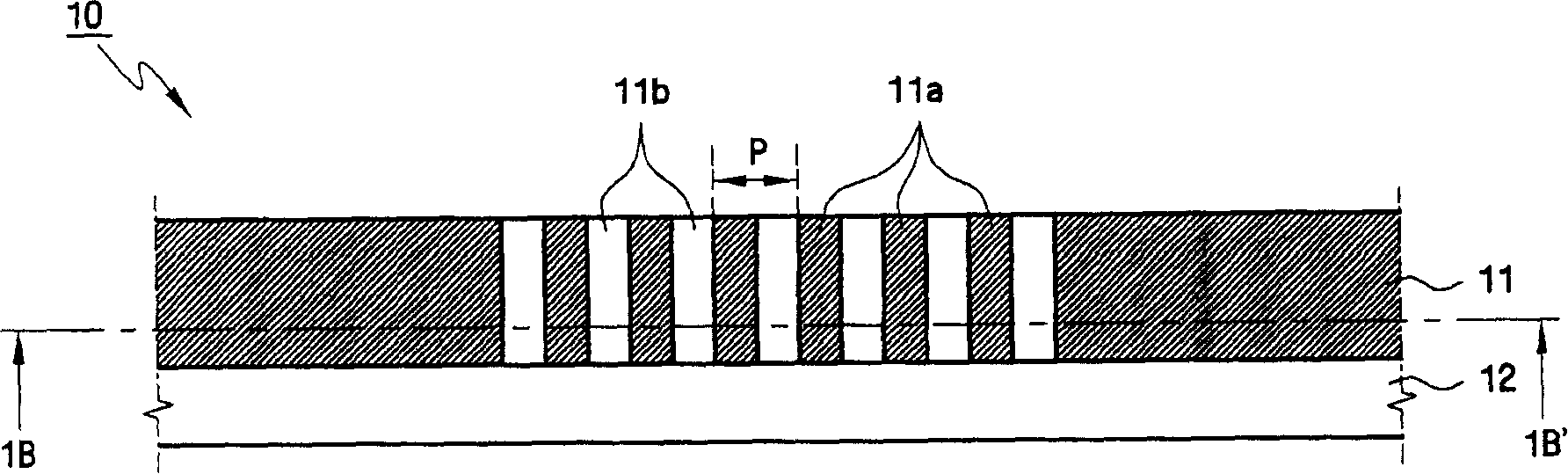
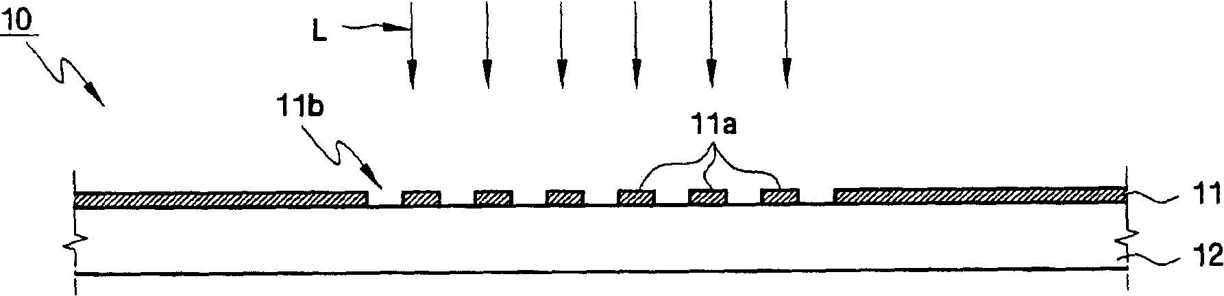
[0052] A photomask and a method of using the photomask according to an embodiment of the present invention, which uses a photomask structure for improving the photolithography process window, and makes focus detection a possible. It should be understood that the drawings are schematic illustrations only, wherein thicknesses and dimensions of various elements, layers and regions are not to scale but are instead exaggerated for clarity. It will also be understood that when a layer is described as being "on" or "over" another layer or substrate, such layer can be directly on the other layer or substrate, or intervening layers may be present. It should also be understood that reference numerals used throughout the drawings indicate identical or similar elements or elements having identical or similar functions.

[0053] Figure 5A and 5B A photomask according to an exemplary embodiment of the present invention is schematically illustrated. in particular, Figure 5A is a top p...


PUM

PropertyMeasurementUnit
transmittivityaaaaaaaaaa

Abstract

Systems and methods are provided for detecting focus variation in a lithographic process using photomasks having test patterns adapted to print test features with critical dimensions that can be measured and analyzed to determine magnitude and direction of defocus from a best focus position of an exposure tool during the lithographic process.

Description

technical field [0001] The present invention generally relates to systems and methods for detecting focus changes in photolithographic processes. More specifically, the present invention relates to a method of constructing a photomask having a test pattern suitable for printing test features having critical dimensions that can be measured and analyzed to determine the optimum The magnitude and direction of the defocus at the focus position. Background technique [0002] Photolithography is an integral process in the manufacture of semiconductor integrated circuits (ICs). Typically, photolithography involves coating a semiconductor wafer (or substrate) with a photoresist layer and directing the photoresisted wafer (or substrate) through a photomask with an image of the integrated circuit using an actinic light source (such as an excimer laser, mercury lamp, etc.) Resist exposure. For example, a photolithography tool such as a deep UV stepper can be used to project light on...

Claims


Application Information

Patent Timeline
Patent Type & Authority Applications(China)
IPC IPC(8): G03F7/20G03F1/26G03F1/38G03F1/42H01L21/027
Inventor 金淏哲
Owner SAMSUNG ELECTRONICS CO LTD
Why Eureka
Try Eureka