Eureka AIR delivers breakthrough ideas for toughest innovation challenges, trusted by R&D personnel around the world.

Combustion chamber of internal combustion engine

A technology of combustion chamber and internal combustion engine, which is applied in the field of combustion chamber and can solve the problems of residual exhaust gas, exhaustion, residual exhaust gas, etc.

Inactive Publication Date: 2006-11-15
晏家全
View PDF0 Cites 0 Cited by
  • Summary
  • Abstract
  • Description
  • Claims
  • Application Information

AI Technical Summary

Problems solved by technology

The common problem of these traditional internal combustion engine combustion chambers is that since the combustion chamber is fixed and immutable and occupies a fixed volume, it is impossible to exhaust the exhaust gas in the combustion chamber at the end of the exhaust stroke, resulting in the exhaust gas remaining in the combustion chamber There is such a record in the first chapter, page 17, of "Automobile Structure" published by People's Communications Publishing House: "Because the combustion chamber occupies a certain volume, it is impossible to exhaust the exhaust gas at the end of the exhaust stroke. This part The exhaust gas left behind is called residual exhaust gas"
It can be seen that since the combustion chamber occupies a fixed volume, the technical problem of residual exhaust gas is caused.

Method used


Image

  • Combustion chamber of internal combustion engine
  • Combustion chamber of internal combustion engine
  • Combustion chamber of internal combustion engine

Examples


Embodiment Construction

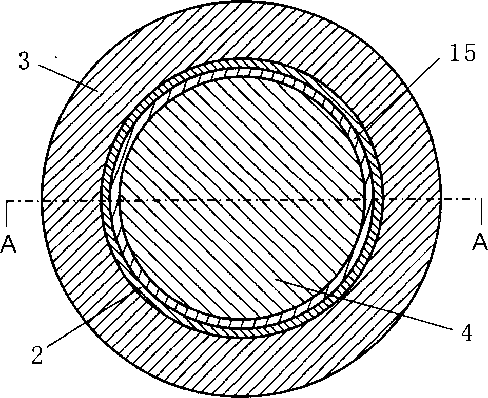
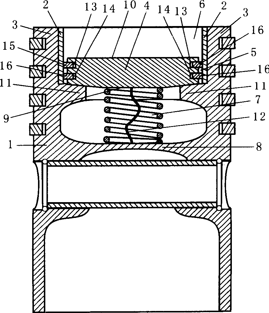
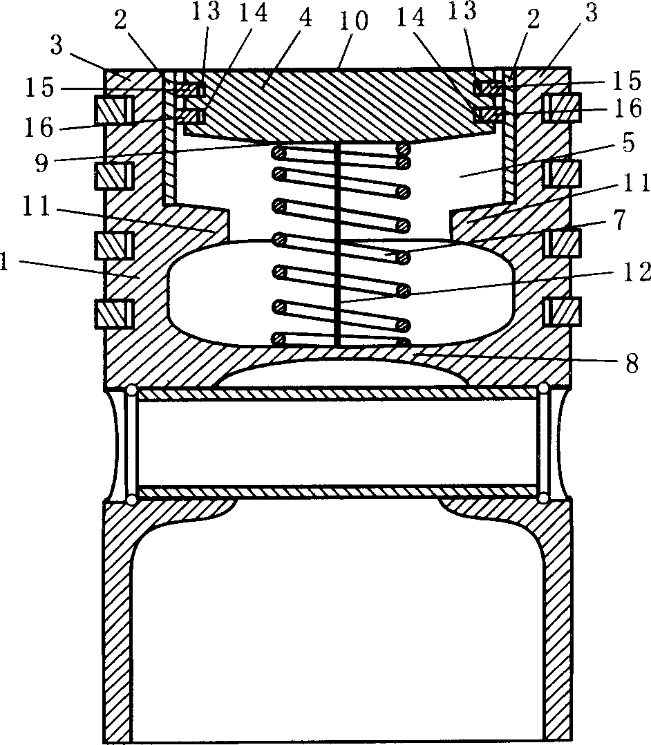
[0019] Depend on figure 1 The cylinder piston plan view and figure 2 The top of the cylinder piston shown along the figure 1 It can be seen from the side cross-sectional view of line A-A in the middle that the top of the cylinder piston 1 head is an annular combustion chamber wall body 3, and this annular combustion chamber wall body 3 forms a concavity-shaped (obviously also cylindrical) concave cavity 5, figure 2 The concave space formed by the annular combustion chamber wall body 3 and the conical combustion chamber piston 4 is exactly a unified combustion chamber 6. The combustion chamber piston 4 is made of aluminum alloy or other heat-resistant metal materials. The bottom surface 9 of the combustion chamber piston 4 is externally provided with a spring 7, one end of the spring 7 is connected to the bridge structure 8 connected to the pin seat of the cylinder piston 1, and the other end is supported or connected to the bottom surface 9 of the combustion chamber piston...


PUM


Abstract

There is disclosed a combustion chamber of internal-combustion engines, which includes a combustion chamber wall body, a combustion chamber piston in the wall body cavity and a mechanism disposed outside the bottom of the combustion chamber piston capable of making the combustion chamber piston be in reciprocating motion along the centre-line of the combustion chamber. Using the inventive structure can eliminate the volume of the combustion chamber and reduce the residual waste gas in the combustion chamber via the movement of the combustion chamber piston at the end of the instroke.

Description

technical field [0001] The invention relates to a combustion chamber of an internal combustion engine. Background technique [0002] The combustion chamber of an internal combustion engine is the space in the cylinder that accommodates the combustible mixture for combustion and heat release. It is generally divided into two categories: unified combustion chamber and separate combustion chamber. The common problem of these traditional internal combustion engine combustion chambers is that since the combustion chamber is fixed and immutable and occupies a fixed volume, it is impossible to exhaust the exhaust gas in the combustion chamber at the end of the exhaust stroke, resulting in the exhaust gas remaining in the combustion chamber There is such a record in the first chapter, page 17, of "Automobile Structure" published by People's Communications Publishing House: "Because the combustion chamber occupies a certain volume, it is impossible to exhaust the exhaust gas at the e...

Claims


Application Information

Patent Timeline
Patent Type & Authority Applications(China)
IPC IPC(8): F02B23/00
CPCY02T10/12
Inventor 晏家全
Owner 晏家全
Why Eureka
Eureka Blog
Learn More