Fluid-drop-flowing injection device and quantitative analysing method

A technology of flow injection and droplet, which is applied in the direction of analyzing materials, measuring devices, and material analysis through optical means, and can solve problems that do not involve the process of droplet coalescence and droplet coalescence reaction, and the optimal mixing of samples and reagents It is difficult to guarantee the ratio, increase the consumption of reagents or samples, etc., and achieve the effects of reducing instrument costs, low production costs, and less sample consumption

Inactive Publication Date: 2006-08-09
SHAANXI NORMAL UNIV
View PDF0 Cites 7 Cited by
  • Summary
  • Abstract
  • Description
  • Claims
  • Application Information

AI Technical Summary

Problems solved by technology

[0003] In the traditional flow injection analysis method, since the carrier is usually used to carry the sample zone and mix it with the reaction reagent, in the process of carrying the sample zone and mixing with the reaction reagent, the sample will be diluted due to diffusion, which makes the analysis method Sensitivity is affected
When using a sampling loop to control the injection volume, a large amount of sample solution is required to wash the sampling loop pipe before each injection, which increases the consumption of reagents or samples
In the traditional flow injection analysis process, the reagent is usually in a continuous flow state, and the reagent consumption in the interval between two injections is also very large
When the detection object of the flow injection analysis is the reaction product of the sample and the reagent, not only the sample and the reagent solution are required to be fully mixed, but also the sample and the reagent are mixed to achieve an optimal mixing ratio; in the traditional flow injection, due to the fluid The laminar flow state is in a dominant position in the pipeline. In order to realize the full mixing of the sample and the reagent solution, it is necessary to obtain turbulent flow by weaving the reactor and other means; in the sequential injection analysis, the sample and the reagent solution are realized by the reciprocating motion of the solution. However, these methods will lead to excessive dilution of the reaction product, making it difficult to ensure the optimal mixing ratio of sample-reagent
Similarly, it takes a certain amount of time to fully mix the above samples and reagents, and the analysis frequency of the analytical method is also greatly affected.
[0004] In the disclosed droplet analysis instruments, only the volume measurement of a single droplet and the analysis of the fluorescent components in a single droplet are introduced, and the coalescence of two or more droplets and the coalescence of droplets are not involved. reaction process

Method used


Image

  • Fluid-drop-flowing injection device and quantitative analysing method
  • Fluid-drop-flowing injection device and quantitative analysing method
  • Fluid-drop-flowing injection device and quantitative analysing method

Examples


Embodiment 1

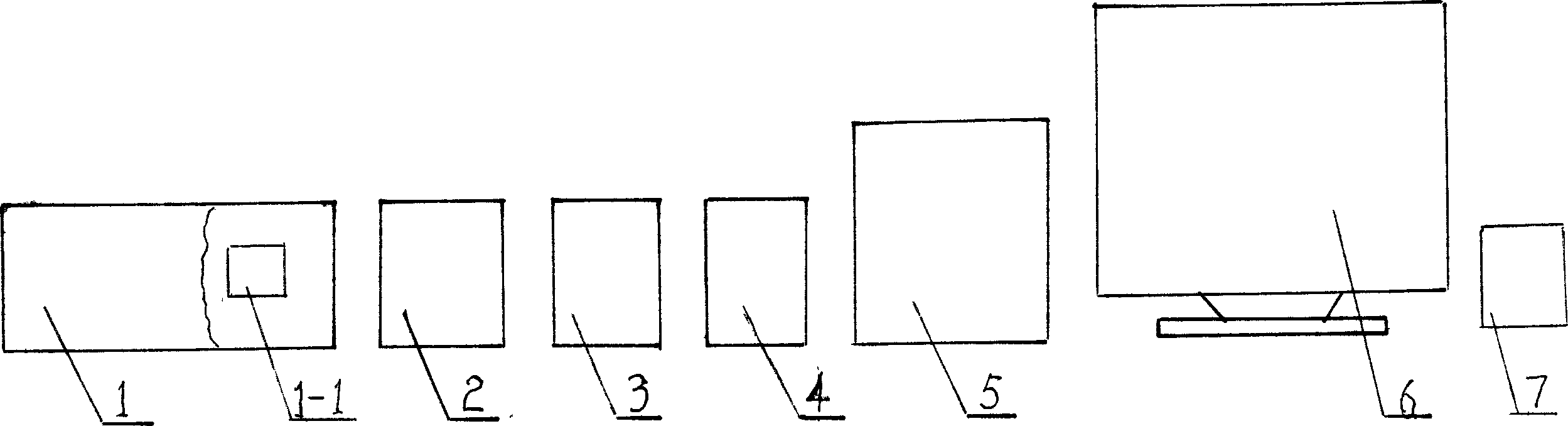
[0043] exist figure 1 Among them, the droplet flow injection device of this embodiment consists of a negative high pressure controller 1, a constant flow pump 2, a syringe pump 4, a peristaltic pump 3, a chemiluminescence instrument 5, a computer 6, a potentiostat 7, and a waste liquid pipe 5-10. Join composition.

[0044] The negative high voltage controller 1 and the potentiostat 7 are connected to the chemiluminescence instrument 5 through wires, communicate with the chemiluminescence instrument 5 through the catheter of the constant current pump 2, and communicate with the chemiluminescence instrument 5 through the catheter of the syringe pump 4, and the chemiluminescence The instrument 5 is connected with the negative high voltage controller 1 through a wire, and the negative high voltage controller 1 is equipped with an A / D converter, and the A / D converter is connected with the computer 6 through a cable. The constant current pump 2, the injection pump 4, the peristalti...

Embodiment 2

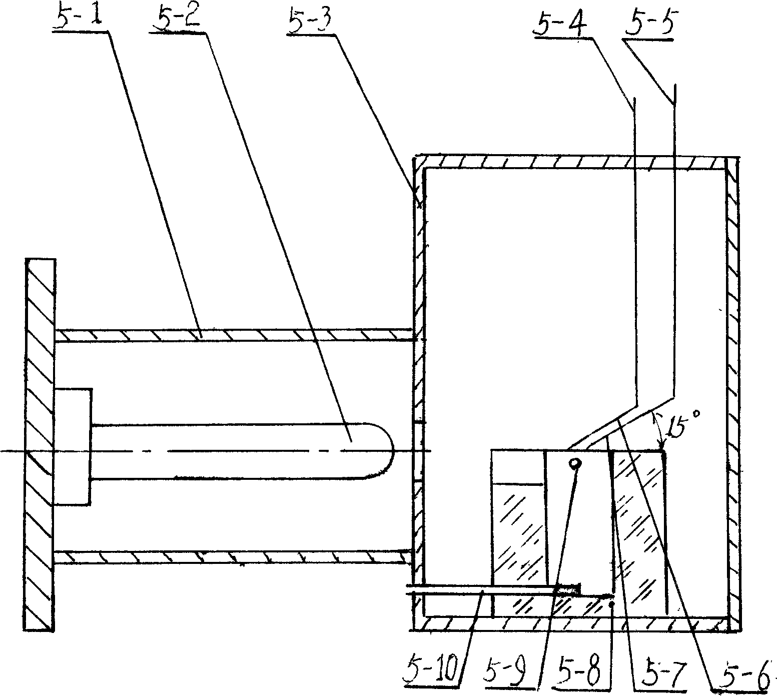
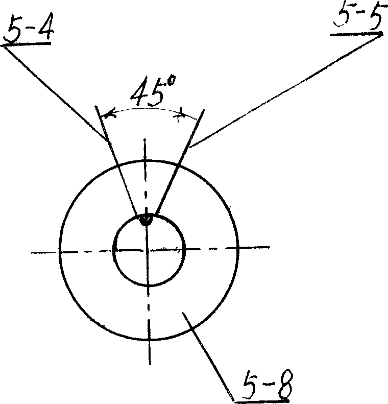
[0068] In this embodiment, the sample inlet tube 5-6 and the reagent inlet tube 5-7 are quartz capillary tubes with an inner diameter of 325 μm, and the electrodes are platinum electrodes. The distance between the nozzles is 0.5mm, the angle between the sample inlet tube 5-6 and the reagent inlet tube 5-7 is 60°, the sample inlet tube 5-6, the reagent inlet tube 5-7 and the luminescence reaction cell 5-8 The included angle of the upper surface is 10°, and the light-emitting reaction pool 5-8 is a light-emitting reaction pool 5-8 made of transparent silicon glass material. Other components and the coupling relationship of the components are the same as in Embodiment 1.

Embodiment 3

[0070] In this embodiment, the sample inlet pipe 5-6 and the reagent inlet pipe 5-7 are quartz capillary tubes with an inner diameter of 500 μm, and the electrodes are platinum electrodes. The distance between the nozzles is 2.0mm, the angle between the sample inlet tube 5-6 and the reagent inlet tube 5-7 is 45°, the sample inlet tube 5-6, the reagent inlet tube 5-7 and the luminescent reaction cell 5-8 The included angle of the upper surface is 30°, and the light-emitting reaction pool 5-8 is a light-emitting reaction pool 5-8 made of transparent silicon glass material. Other components and the coupling relationship of the components are the same as in Embodiment 1.


PUM


Abstract

A liquid drop flow injection unit and quantitative analysis method includes constant flow pump, injector pump, peristaltic pump, negative high pressure controller high pressure controller, chemoluminescence instrument, and computer. Quantitative analysis method includes preparation reagent, preparing sample solution, standard curve and detecting sample. Said invented liquid drop flow injection unit and quantitative analysis method can be used in inorganic ions, organic molecule, medicine etc flow injection analysis.

Description

technical field [0001] The invention belongs to the technical field of testing or analyzing materials by means of determining their chemical or physical properties, and in particular relates to devices in which materials are subjected to chemical reactions, and the progress of the testing reactions or the resulting chemiluminescence. Background technique [0002] Since Ruzicka and Hansen first proposed Flow Injection Analysis (FIA) technology in 1975, flow injection technology combined with detection methods such as ultraviolet, fluorescence, chromatography, atomic spectroscopy, and mass spectrometry has been widely used in the field of analytical chemistry. application. The characteristics of fast, simple and low consumption of flow injection technology are also the goals pursued by all analytical methods. Among the analysis methods combined with flow injection technology, the luminescence analysis method shows the advantages of fast analysis speed, simple equipment, less ...

Claims


Application Information

Patent Timeline
Patent Type & Authority Applications(China)
IPC IPC(8): G01N21/76G01N21/03G06F19/00
Inventor 吕家根齐慧丽齐昕吴丰魁王娟聂迎春
Owner SHAANXI NORMAL UNIV
Why Eureka
Try Eureka