Pre-stress vibrating diaphragm

A pre-stressed, thin-film technology, applied in the direction of flat diaphragm, diaphragm fixing/tightening, diaphragm structure, etc., to achieve the effect of improving sound quality, small phase distortion, and reducing harmful vibrations

Active Publication Date: 2011-11-23
程光
View PDF0 Cites 0 Cited by
  • Summary
  • Abstract
  • Description
  • Claims
  • Application Information

AI Technical Summary

Problems solved by technology

[0006] The purpose of the present invention is to provide a new type of prestressed diaphragm, the technical problem to be solved is to change the free relaxation state of the diaphragm and improve the mechanical properties of the diaphragm for the existing problems of the traditional loudspeaker or microphone diaphragm. Reduce the distortion and deformation of the diaphragm after being stressed, and effectively transmit the vibration force

Method used


Image

  • Pre-stress vibrating diaphragm
  • Pre-stress vibrating diaphragm
  • Pre-stress vibrating diaphragm

Examples


Embodiment Construction

[0036] The present invention will be further described in detail below through specific embodiments in conjunction with the accompanying drawings.

[0037] To facilitate understanding, before describing specific embodiments, a brief introduction to the structure of the present invention will be given.

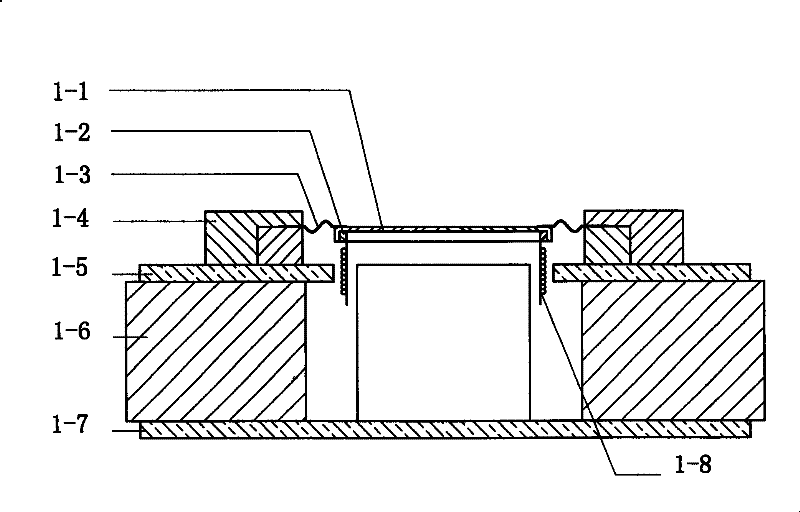
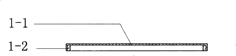
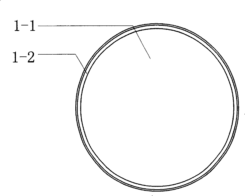
[0038] figure 1 Shown is a loudspeaker of the present invention, including a rigid diaphragm frame 1-2 connected to the voice coil 1-8, the diaphragm 1-1 is a tensioned pre-stressed diaphragm, the diaphragm frame 1-2 Fixed tension pre-stressed film. The frame 1-2 of the pre-stressed diaphragm is connected to the voice coil 1-8, and the edge of the pre-stressed diaphragm is connected to the bracket 1-4 through an elastic support 1-3. The functions and connection methods of other components are the same as those of traditional speakers. The bracket 1-4 is connected to the magnetic conductive plate 1-5, the magnet 1-6 and the magnetic conductive column 1-7.

[0039] Such as Figure 4 ...


PUM


Abstract

A vibration film of prestress is prepared as connecting rigid vibration frame with voice coil, fixing prestress film on vibration frame tightly, fixing partial vibration frame on voice coil and connecting another partial vibration frame with rack through an elastic support, connecting edge of vibration frame with rack through an elastic support.

Description

Technical field [0001] The invention relates to a loudspeaker, a microphone and its diaphragm, in particular to a diaphragm that can effectively improve the frequency characteristics and sound quality of the loudspeaker and the microphone, reduce distortion, and improve the sensitivity and clarity of the loudspeaker and the microphone. Background technique [0002] Traditional speakers such as Figure 8 As shown, it is mainly composed of folding ring 8-1, diaphragm 8-2, bracket 8-3, centering piece 8-4, magnetic plate 1-5, magnet 1-6, magnetic column 1-7 and sound Circles 1-8 and so on. When the signal current flows through the voice coil 1-8, the voice coil 1-8 moves under the action of electromagnetic force in the magnetic field. The voice coil 1-8 is connected to the root of the diaphragm 8-2 to drive the diaphragm 8-2 to move. The force is transmitted from the root of the diaphragm 8-2 to the outside, acting on the air before and after it, causing it to vibrate, thereby produ...

Claims


Application Information

Patent Timeline
Patent Type & Authority Patents(China)
IPC IPC(8): H04R7/00H04R7/04H04R7/16H04R9/02
Inventor 程光
Owner 程光
Why Eureka
Try Eureka