
Light-reflector and planar light source using same

A technology of light reflector and reflectivity, applied in the direction of light guide, optics, optical components, etc., can solve the problems of peeling, peeling, peeling of white polyolefin film surface, etc., and achieve excellent processability, excellent optical properties, and good brightness. Effect

Active Publication Date: 2006-07-26
MITSUBISHI CHEM CORP
View PDF14 Cites 11 Cited by
  • Summary
  • Abstract
  • Description
  • Claims
  • Application Information

AI Technical Summary

Problems solved by technology

Compared with the light reflector using white polyester film, the color tone of the light reflector using white polyolefin film has less change (for example, Japanese Patent Laid-Open No. 8-262208 and WO03 / 014778 communique), but it sticks to metal or other plates. When combined with various molding processes, the light reflector using the white polyolefin film has problems such as peeling and peeling due to the destruction of the adhesive part
Moreover, even when the surface is protected with a protective tape depending on the situation, problems such as surface peeling of the white polyolefin film still occur due to the adhesive force
[0005] In addition, with the enlargement of display objects, further improvement in brightness is required, and the conventional white polyester film or white polyolefin film cannot fully meet this requirement, so a light reflector with higher brightness is required

Method used


Image

  • Light-reflector and planar light source using same
  • Light-reflector and planar light source using same

Examples


Embodiment 1

[0062] Composition (A) and composition (B) obtained by mixing the materials described in Table 1 according to the ratio shown in Table 2 were melted at 250°C using 3 extruders (2 for composition (B)) kneading. Then, it is supplied to a co-extrusion die, and (B) is laminated on both sides of (A) in the die, extruded as a sheet, and cooled to about 60°C with a cooling roll to obtain (B) / (A) / (B) laminate.

[0063] The above-mentioned laminate was reheated to 145° C., longitudinally stretched by utilizing the difference in linear speed of a plurality of roll groups, and then reheated to about 150° C. and transversely stretched by a tenter. Next, after performing softening treatment at 160°C, it was cooled to 60°C, and a laminated film with a three-layer structure was obtained after cutting off burrs. The stretch ratios in the longitudinal and transverse directions and the thickness of each layer are shown in Table 2. The above laminated film was used as a light reflector.

Embodiment 2~5

[0065] The composition (A) obtained by mixing the materials described in Table 1 according to the compounding ratio shown in Table 2 was melt-kneaded at 250° C. using an extruder. Then it is extruded in the form of flakes and cooled to about 60°C with a cooling roll to obtain flakes. After the above-mentioned sheet was heated to 145°C, it was longitudinally stretched using the difference in line speed of a plurality of roller groups.

[0066]The composition (B) obtained by mixing the materials described in Table 1 according to the ratio shown in Table 2 was melt-kneaded using two extruders, extruded (B) in the mold as the outside and laminated on the above to obtain Both sides of the sheet were stretched to obtain a (B) / (A) / (B) laminate. Next, the laminate was heated again to 160° C. and stretched transversely with a tenter.

[0067] Then, after performing a softening treatment at 160°C, it was cooled to 60°C, and a laminated film with a three-layer structure was obtained af...


PUM

PropertyMeasurementUnit
strengthaaaaaaaaaa
particle sizeaaaaaaaaaa
thicknessaaaaaaaaaa

Abstract

A light reflector having a laminate film that comprises a substrate layer (A) containing a thermoplastic resin and a filler and stretch in at least one direction to have an areal draw ratio of from 1.3 to 80 times and a thermoplastic resin-containing layer (B), wherein the light reflector has a whole ray reflectance of at least 95% and a surface strength of at least 250 g. The light reflector has good optical properties and good workability in that, when stuck to various plates and shaped, it hardly looses, drops and peels from the substrate plates.

Description

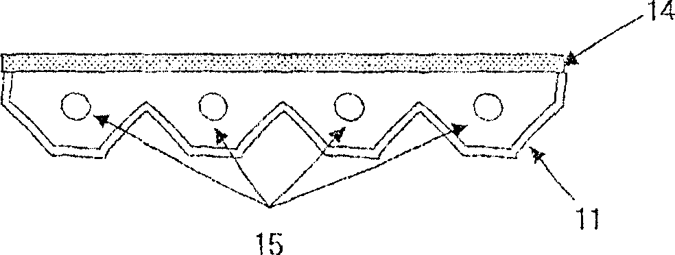
technical field [0001] The present invention relates to a light reflector which is useful as a light reflection plate used in a surface light source device, a reflector, and a light reflection member used in various lighting fixtures, and is not likely to cause surface damage even if various processes are performed. It is a light reflector with excellent workability. Background technique [0002] A backlight type liquid crystal display equipped with a built-in light source is widely used. Among the built-in light sources of the backlight type, the typical structure of the direct type backlight is as follows: figure 1 As shown, it consists of light sources such as an outer cover 11 that acts as a structure and a light reflector, a diffuser 14, and a cold cathode lamp 15. The typical structure of edge-lit backlight is as follows: figure 2 As shown, it is composed of a light guide plate, a light reflector 11 , a diffusion plate 14 , and light sources such as cold cathode la...

Claims


Application Information

Patent Timeline
Patent Type & Authority Applications(China)
IPC IPC(8): G02B5/08F21V8/00G02F1/13357G02F1/1335
Inventor 上田隆彦小山广高桥友嗣
Owner MITSUBISHI CHEM CORP
Learn More