
Switching type controller

A control device and switching technology, which is applied to output power conversion devices, control/regulation systems, and conversion equipment with intermediate conversion to AC, etc. and cost reduction effect

Active Publication Date: 2006-06-07
SYST GEN
View PDF1 Cites 22 Cited by
  • Summary
  • Abstract
  • Description
  • Claims
  • Application Information

AI Technical Summary

Problems solved by technology

However, the above-mentioned prior art cannot meet the precise output voltage and maximum output current at the same time

Method used


Image

  • Switching type controller
  • Switching type controller
  • Switching type controller

Examples


Embodiment Construction

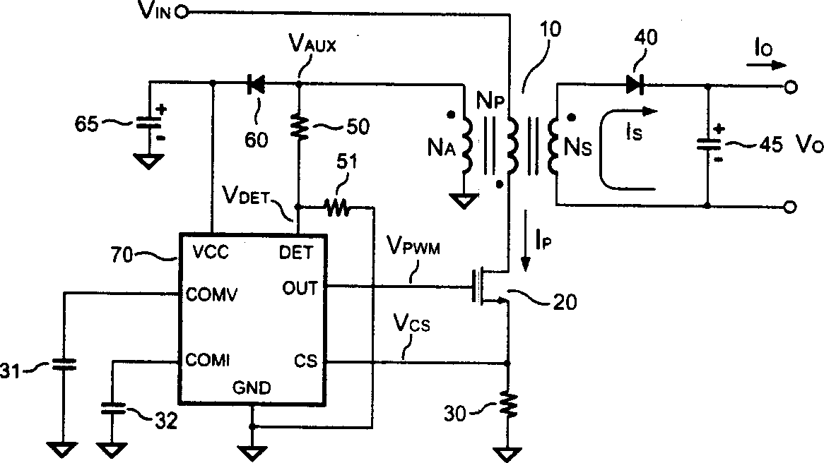
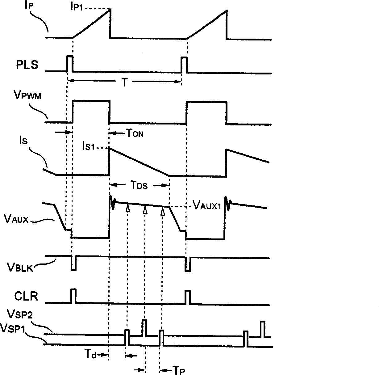
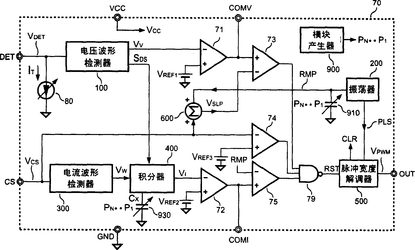
[0065] figure 1 It is a power supply in the present invention. The power supply includes a transformer 10 having an auxiliary winding NA, a primary winding NP and a secondary winding NS. A switching power switch 20 is used for switching the current flowing through the primary side winding NP of the transformer 10, and the primary side winding NP of the transformer 10 is connected to the input voltage VIN of the power supply. A current sensing device 30 is connected to the transformer 10 through the switching power switch 20 for sensing the primary side current of the transformer 10 . A switching signal VPWM is connected to the control terminal of the switching power switch 20 to control the switching action of the switching power switch 20, and the output voltage VO and the maximum output of the power supply can be stably adjusted at the secondary side winding NS terminal of the transformer 10. Current IO. A controller 70 is connected to the control terminal of the switchin...


PUM


Abstract

This invention relates to a switch control device connected to the primary side of a transformer to control the switch of the transformer to provide a DC power output including: a switch power switch with its output connecting to one end of the primary side of the transformer and the other connected with the input voltage, a current sensing device connected with the other output end of the switch to sense current signals by the switch action of the switch, a controller connected with the control end of the switch and the current sensing device and connected with the assist winding by a bleeder to get the voltage signals and discharge time from the winding and get current signals from the sensing device and output switch signals to the control end.

Description

technical field [0001] The invention relates to a switching control device used in a control circuit of a power supply, in particular to a switching control device for a switching mode power supply. Background technique [0002] Various power supplies have been widely used to provide stable and regulated voltage and current. In consideration of safety, an off-line power supply must provide galvanic isolation between its primary side and secondary side. In this case, a switching control device is configured on the primary side of the power supply, and an optical-coupler and a secondary-side regulator must be used to stabilize and adjust the off-line power supply output voltage and / or output current. In order to save the number of components and eliminate the need for secondary-side feedback circuits, primary-side control techniques have been proposed, such as US Patent No. 4,302,803 published on November 24, 1981. However, the above-mentioned prior art cannot satisfy the p...

Claims


Application Information

Patent Timeline
Patent Type & Authority Applications(China)
IPC IPC(8): H02M3/28H02M3/335
Inventor 杨大勇洪国强林振宇李俊庆邱绍伟
Owner SYST GEN
Learn More