Eureka AIR delivers breakthrough ideas for toughest innovation challenges, trusted by R&D personnel around the world.

Electronic transformer/inductor devices and methods for making same

A technology for inductors and transformers, applied in the field of electronic transformers/inductor devices and their manufacturing, can solve the problem of heat being not easily dissipated, and achieve the effects of excellent repeatability, simplified electrical connection, and good performance

Inactive Publication Date: 2006-06-07
MULTI FINELINE ELECTRONIX INC
View PDF0 Cites 0 Cited by
  • Summary
  • Abstract
  • Description
  • Claims
  • Application Information

AI Technical Summary

Problems solved by technology

[0005] The power transformer constructed as shown also has the disadvantage that the heat generated by the resistive losses in the coils is not easily dissipated because the E-core and cap separate these coils from the heat sink

Method used


Image

  • Electronic transformer/inductor devices and methods for making same
  • Electronic transformer/inductor devices and methods for making same
  • Electronic transformer/inductor devices and methods for making same

Examples


Embodiment

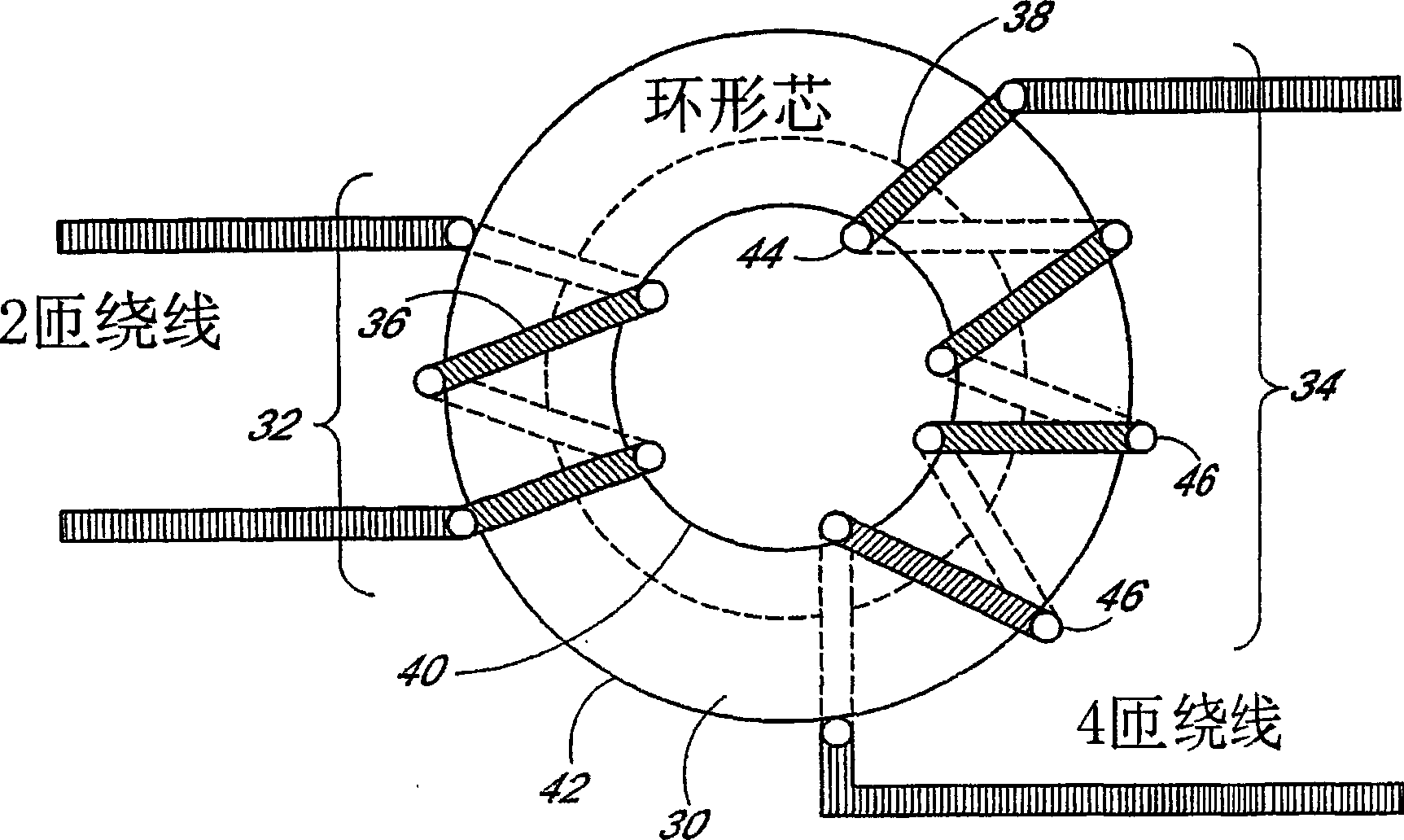
[0053] Many inductive devices such as low frequency power transformers require a magnetic core with a relatively high relative permeability, typically in the range of 10,000-100,000. However, improvements provided by the preferred embodiment are available for lower and higher values, for example in the range of 1000-1000000. Certain metals and metal alloys provide these high flux densities, including steel, iron, silica Iron, permalloy 78, Mumetal, refined iron, and supermalloy ). While these high flux densities can provide significant advantages in constructing transformers and inductors, the low resistivity of metals allows induced eddy current flow, which negates the advantages of higher flux densities. The induced eddy currents 300 generated by the magnetic flux flowing in the metal core are shown in Figure 13 middle. These eddy currents are reduced in current metal cored transformers / inductors by forming a toroidal or E-shaped core out of laminated metal E-strips, wit...


PUM

PropertyMeasurementUnit
thicknessaaaaaaaaaa
widthaaaaaaaaaa

Abstract

The present invention relates to a method of forming inductive elements, such as inductors, chokes and transformers used as an integral part of the manufacture of PCBs or FLEXs, preferably from ferromagnetic materials. In a preferred embodiment, holes (56, 58) are formed through the ferromagnetic substrate (50) and plated with a conductive material. The placement of these holes and subsequent design will form the inductive element in the plane of the medium in which the device is formed; the substrate (50) for the magnetic core (90). By employing this approach, the inductive element can be minimized to a physical size compatible with the demands of modern surface mount technology (SMT) for integrated circuits (ICs). This process also allows these components to be fabricated using mass production techniques, thereby avoiding the need to manipulate individual devices during the fabrication process. In another preferred embodiment, a series of thin, concentric high permeability rings (315) are etched on the substrate (330) to provide high permeability transformers and inductors with minimal eddy current effects.

Description

field of invention [0001] The present invention relates to inductive components and methods of manufacturing these components. Background of the invention [0002] Inductive components are usually manufactured with a ferromagnetic core and a coil of insulated wire. Ferromagnetic cores are usually toroidal cores, rod cores, or assemblies consisting of a ferromagnetic portion in the shape of the lower part of the E and a ferromagnetic cap connecting the three legs of the E, as shown in Figure 1. [0003] Toroidal and rod cores are wound manually or automatically with insulated copper wire to form a large number of multi-turn coils for a transformer or a single coil for an inductor. The assembly is then typically encapsulated to protect the copper wires. Circuit contacts are formed by the soldered ends of the wires as required by the application. This solution has high labor costs due to handling the individual components. There is also considerable variability in electroni...

Claims


Application Information

Patent Timeline
Patent Type & Authority Applications(China)
IPC IPC(8): H01F27/00H01F27/24H01F27/28
Inventor P·A·哈丁
Owner MULTI FINELINE ELECTRONIX INC
Why Eureka
Eureka Blog
Learn More