
Permanent-magnet dimagnetic combined suspension rotor micro gyroscope

A suspension rotor and magnetic combination technology, applied in the direction of rotating gyroscope, etc., can solve the problems of poor suspension and rotation stability, mutual interference between suspension and rotation, and unfavorable gyro function.

Inactive Publication Date: 2006-05-24
SHANGHAI JIAO TONG UNIV
View PDF0 Cites 9 Cited by
  • Summary
  • Abstract
  • Description
  • Claims
  • Application Information

AI Technical Summary

Problems solved by technology

[0004] Although the suspension rotor design scheme of Joe Nhut Ho of the University of Washington in the United States can realize the suspension and rotation of the rotor, there are several shortcomings and shortcomings in order to become a gyroscope, especially a micro-gyroscope using micro-processing technology: 1) The design scheme has no sensor , essentially cannot constitute a gyro sensor
2) Suspension and rotation both use electromagnetic fields, so suspension and rotation interfere with each other, and the stability of suspension and rotation becomes poor. It has a principle defect to become a gyroscope
3) The rotor adopts an equilateral triangle structure, and permanent magnets are arranged at the three vertices of the triangle. The arbitrary radial moments of inertia of the plane perpendicular to the inertial axis of this structure are not equal, which is very unfavorable for the realization of the gyro function
4) AC current is passed through the rotating drive coil, and the heating phenomenon is relatively serious
5) The design includes a spatially complex arrangement of drive coils, which is not convenient for micromachining, and is limited in mass production and cost reduction

Method used


Image

  • Permanent-magnet dimagnetic combined suspension rotor micro gyroscope
  • Permanent-magnet dimagnetic combined suspension rotor micro gyroscope
  • Permanent-magnet dimagnetic combined suspension rotor micro gyroscope

Examples


Embodiment Construction

[0025] Such as figure 1 As shown, the present invention includes: an upper stator 1 , a lower stator 3 , a support ring 2 and a rotor 4 . The connection mode is that the upper stator 1, the lower stator 3 and the support ring 2 form a cavity, and the rotor 4 is located in this cavity.

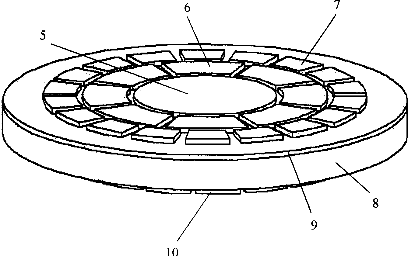
[0026] Such as Figure 2-3 As shown, the upper stator 1 is provided with a dielectric material layer 8, an insulating support layer 9 is provided on the upper surface of the dielectric material layer 8, and a common electrode 5 is provided at the center of the outer surface of the insulating support layer 9, and then the insulating support is provided from the inside to the outside. The outer surface of the layer 9 is provided with 8 sector-shaped detection moment electrodes 6 uniformly arranged in the circumferential direction, and 18 sector-shaped rotating electrodes 7 uniformly arranged in the circumferential direction, and a permanent magnetic material layer 10 is provided on the lower sur...


PUM


Abstract

The micro gyro includes upper stator, support ring, lower stator and rotor. The upper stator includes magnetic dielectric material layer; and layers of insulation support layer are setup on upper surface of the magnetic dielectric material layer. Common electrode is setup at center of surface of the insulation support layer. 8 pieces of moment added electrode for detecting sector and 18 pieces of fan shaped rotating electrode are setup from inner to outer on the insulation support layer. Permanent magnetic material layer is setup at low surface of the magnetic dielectric material layer. Structure of the lower stator is same as to structure of the upper stator. The rotor is a rotor with external teeth or rotor containing inner teeth. Features are: micro power dissipation, small size, no need of manual assembly, high reliability, low cost and batch production.

Description

technical field [0001] The invention relates to a device in the field of micro-electromechanical technology, in particular to a permanent-magnet-medium-magnetic combination levitation rotor as a gyroscope. Background technique [0002] Micro-mechanical gyroscopes are the product of the combination of MEMS (micro-electromechanical systems) technology and gyroscope technology, and there are two types: vibration type and suspended rotor type. The vibrating micro-gyroscope works using the Coriolis effect, and the size is within a few millimeters. The detection quality of the vibrating micro-gyroscope is connected to the substrate through a mechanical structure. Due to its own limitations and some difficulties in micro-processing, the drift accuracy is at a low-to-medium level. . The suspended rotor micro-gyroscope uses electromagnetic force or electrostatic force to separate the detection micro-rotor from the substrate, and its drift accuracy can reach the inertial level. [0...

Claims


Application Information

Patent Timeline
IPC IPC(8): G01C19/24G01C19/02
Inventor 张卫平陈文元刘武赵小林
Owner SHANGHAI JIAO TONG UNIV
Learn More