
Laser processing machine and method

A laser processing machine, laser processing technology, applied in metal processing, laser welding equipment, metal processing equipment and other directions, can solve the problem of unprocessable objects display and so on

Inactive Publication Date: 2006-05-17
HITACHI SEIKO LTD
View PDF1 Cites 37 Cited by
  • Summary
  • Abstract
  • Description
  • Claims
  • Application Information

AI Technical Summary

Problems solved by technology

However, for observation, when the same optical path as the laser light path is used for illumination, if the surface shape of the processing object or the background of the processing object is in a mirror state, it will form frontal reflected light and the processing object can be displayed, but If the processing object has no mirror surface, the processing object cannot be displayed, and it is difficult to correct the processing part

Method used


Image

  • Laser processing machine and method
  • Laser processing machine and method
  • Laser processing machine and method

Examples


Embodiment Construction

[0026] Next, embodiments of the laser processing machine and the laser processing method of the present invention will be described with reference to the drawings.

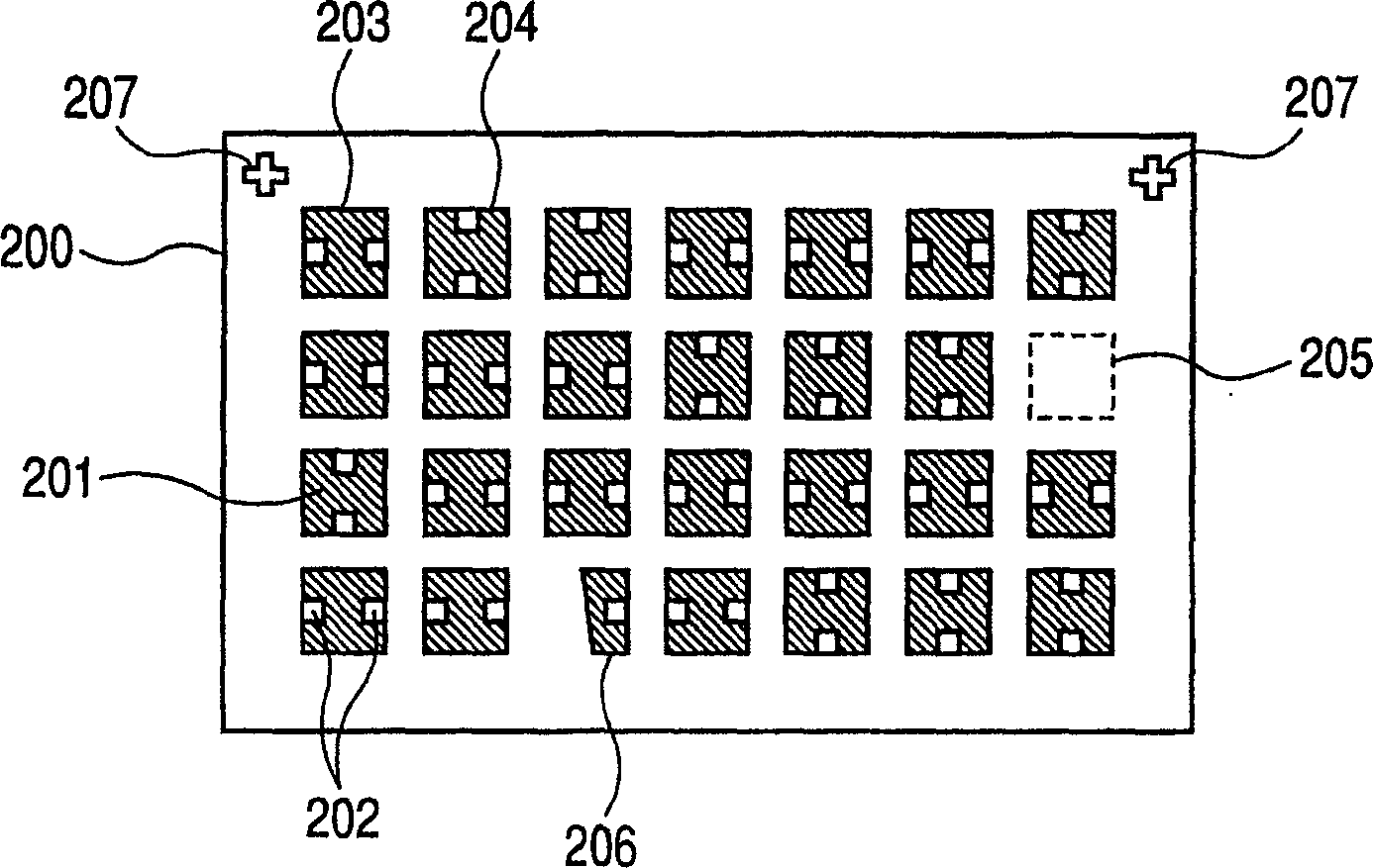
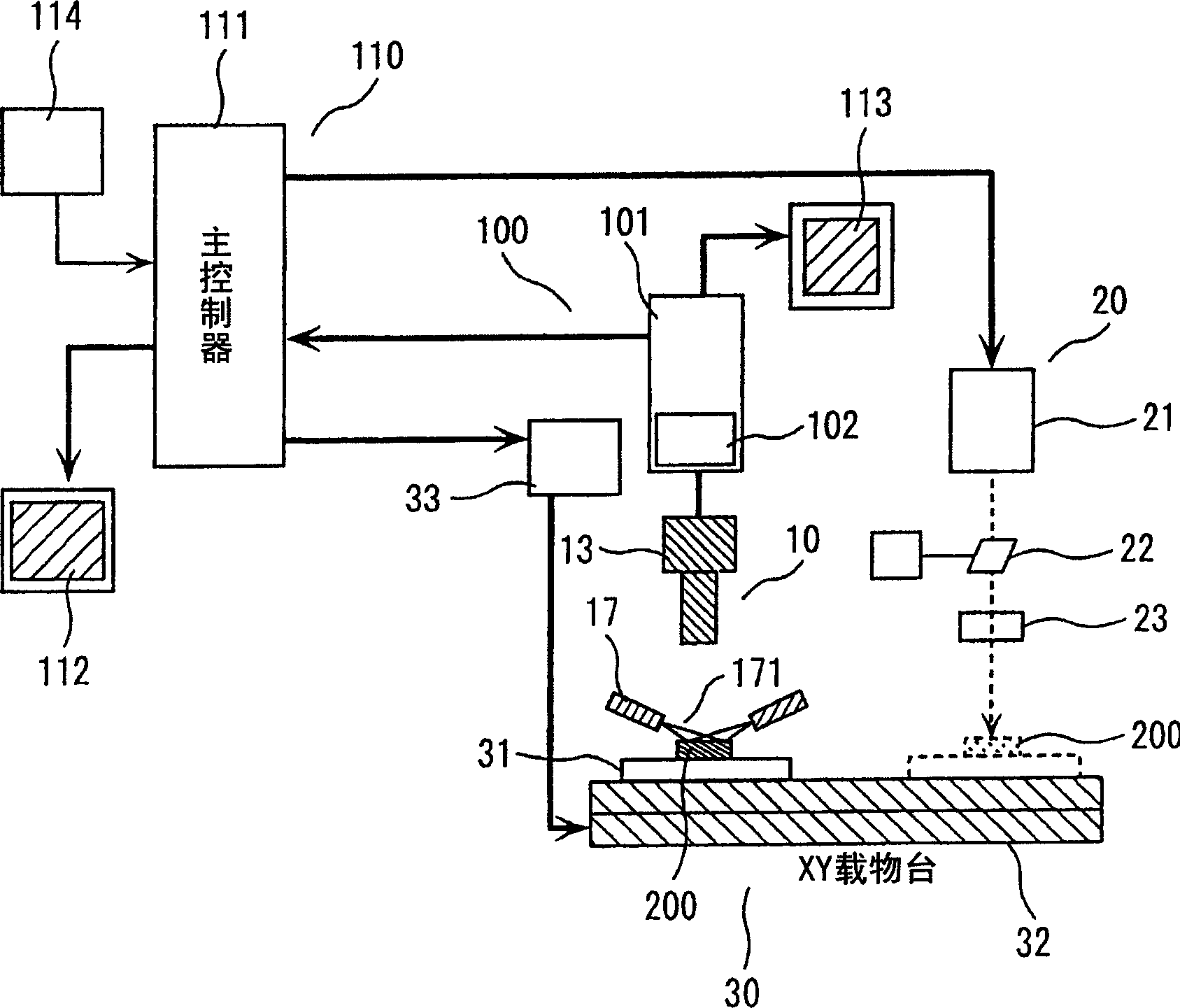
[0027] figure 1 is a diagram showing an example of a workpiece to be processed, figure 2 It is a block diagram showing an embodiment of a laser processing machine equipped with a processing position compensation mechanism according to the present invention.

[0028] First, refer to figure 1 and Figure 7 Describes the workpiece to be processed. figure 1 shows an enlarged plan view of workpiece 200, Figure 7 Shows an enlarged cross-sectional view of a part of the workpiece. The workpiece 200 is based on the reference position of the reference mark 207. For example, many tiny chip parts 201 of about 1mm square are arranged on a sheet 198 such as polyimide, and it is fixed with an adhesive or the like. It is covered with a protective film 199. Then, it is necessary to punch holes in the protective film 199 t...


PUM

PropertyMeasurementUnit
angle of incidenceaaaaaaaaaa
sizeaaaaaaaaaa

Abstract

The laser processing machine of the present invention can perform high-efficiency and high-precision laser processing on workpieces where many processing objects are arranged, and deviations of the center coordinates of the processing parts within the processing tolerance or deviations of the loading positions of the processing objects occur. The laser processing machine of the present invention has: a workpiece (200) that is loaded with many processing objects; an XY stage (32) that moves in the XY direction according to the numerical control data; it is arranged on the image capturing station and has an oblique lighting optical system (17) and the image pick-up head (10) of detection optical system; Be arranged on the laser processing station, have laser source (21), obtain according to the deflection direction obtained from the image signal of each processing object obtained by the above-mentioned image pick-up head Control data, XY light deflector (22) for deflecting laser beam in XY direction and laser machining head (20) for illuminating lens (23) to incident deflected laser beam into each processing object from vertical direction.

Description

technical field [0001] The present invention relates to a laser processing machine and a laser processing method for processing holes by irradiating laser light on a plurality of processing objects arranged on a workpiece loaded on a numerically controlled XY table. Background technique [0002] In conventional CNC laser processing machines, the design center coordinates of the holes to be processed are recorded in the processing program in advance, and then the laser is irradiated according to this processing program. (See Patent Document 1 - Japanese Patent Application Laid-Open No. 2000-343260) [0003] In recent years, the miniaturization of processing objects has progressed rapidly, and many processing objects are collected and arranged together for processing. [0004] However, because the allowable processing area of ​​the micro-processing object is very small, due to the deviation of the center coordinate of the processing part within the processing tolerance, and t...

Claims


Application Information

Patent Timeline
Patent Type & Authority Applications(China)
IPC IPC(8): B23K26/00B23K26/02B23K26/08
CPCB23K26/03B23K26/032B23K26/04B23K26/0853B23K26/043B23K2101/40B23K26/02
Inventor 胜田大辅野本峰生吉村和士
Owner HITACHI SEIKO LTD
Learn More