
Thermal die casting machine

A die-casting machine and casting hole technology, which is applied in the field of hot die-casting machines, can solve problems such as limitations, reduced casting quality, and poor casting efficiency

Inactive Publication Date: 2006-05-17
菱沼压铸机株式会社
View PDF0 Cites 3 Cited by
  • Summary
  • Abstract
  • Description
  • Claims
  • Application Information

AI Technical Summary

Problems solved by technology

[0006] However, in conventional die-casting machines, due to its basic structure, a passage (gate A63 and gate B64) must be provided between the tip of the nozzle 56 and the metal casting hole 62 to change the flow direction of the molten metal 51, Therefore, in order to completely fill the molten metal 51 in the metal casting hole 62, there is a lot of loss of casting pressure, and there are problems such as poor casting efficiency.
Moreover, there is air in the passage (gate A63 and gate B64), and when the molten metal is pressed in, the molten metal 51 in the metal casting hole 62 is likely to be mixed with air, resulting in a problem of lower casting quality.
[0007] Also, in the basic structure of the generally known die-casting machine, the extruding of the die-casting finished product must be performed through the hydraulic pressure cylinder 65 arranged behind the movable plate 60, so it must be driven from the movable metal mold. 61 for extrusion, subject to great restrictions

Method used


Image

  • Thermal die casting machine
  • Thermal die casting machine
  • Thermal die casting machine

Examples


Embodiment Construction

[0037] Embodiments of the present invention will be described below with drawings.

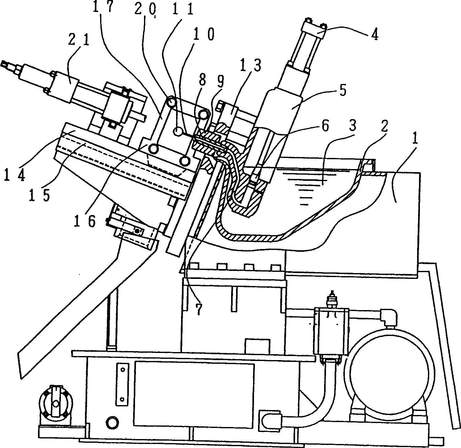
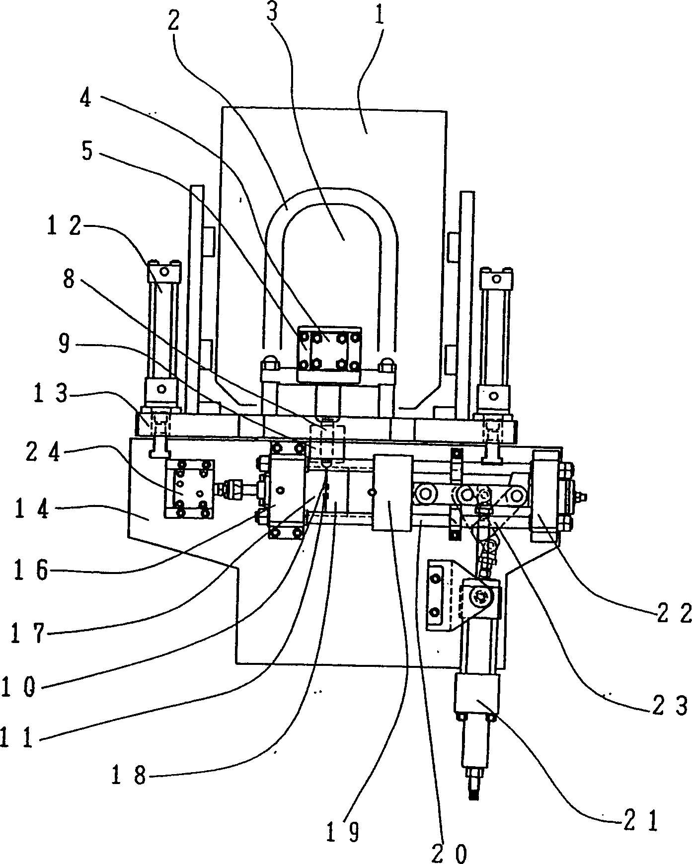
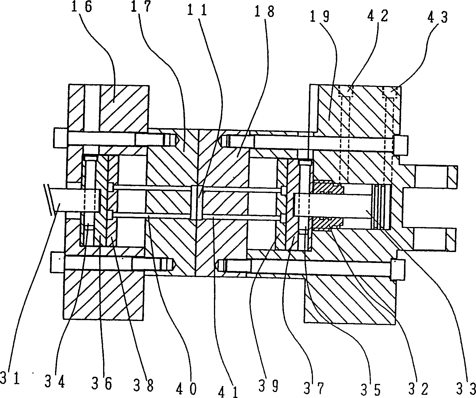
[0038] figure 1 It is a sectional view of a side part of a thermal die casting machine according to an embodiment of the present invention. figure 2 It is another embodiment of the present invention, a top view of a hot combustion chamber die casting machine. figure 1 and figure 2 The hot die-casting machine shown is basically composed of the following two devices, including: an injection device, which can press the molten metal 3 melted in the melting furnace 1 into the casting hole 11 of the metal mold, and an opening Die device can take out its die-casting finished product after the molten metal 3 in casting hole 11 li of metal mold through pressurization is cooled.

[0039] First, the injection device will be described. Using a heater installed in the melting furnace 1 and not shown in the figure to heat the crucible (pot) 2, the metal in the crucible (pot) 2 will be melted into a ...


PUM


Abstract

The present invention provides one kind of hot pressure casting machine capable of producing high quality castings with less bubble and good look and adopting metal mold with high freedom. The metal mold with mold opener in right angle to the injector is connected hermetically to the nozzle of the injector, and molten metal is injected through the connection. The mold opener is shifted through indirect driving of the pedestal the mold opener is set on. There are two optional pressing out oil cylinders, including one located behind the fixing disc and the other located inside the movable disc.

Description

technical field [0001] The invention relates to a thermal die-casting machine, which is characterized in that it is a device for injecting molten metal into a metal mold at high pressure, and the molten metal is filled in a crucible (pot) before injection. The die casting machine is located in a gooseneck assembly filled with molten metal. Background technique [0002] The structure of the generally known hot die casting machine is as follows: Figure 4 shown. [0003] As shown in this figure, its structure is that the following devices are arranged horizontally in sequence: a movable metal mold 61 on a movable plate 60 driven by a mold clamping cylinder (moldclamping cylinder) (omitted in the figure) and a movable metal mold 61 connected thereto. The metal mold 58 installed on the fixed plate 57 that forms the metal casting hole 62 on the movable metal mold 61 and the injection device that can inject molten metal 51 to the metal casting hole 62 from the bottom of the fixed...

Claims


Application Information

Patent Timeline
Patent Type & Authority Applications(China)
IPC IPC(8): B22D17/02
Inventor 神立润一
Owner 菱沼压铸机株式会社
Learn More