


Quick Research
Generate reliable direction feasibility study reports for your R&D in just a few steps.

Technical Q&A
Discover and master advanced knowledge NOW. Basics, ideas, possibilities, all at once.

Find Solutions
As an expert in R&D theories, this can generate solutions to your technical problems instantly.

Evaluate Feasibility
Analyze your overall solution with one click, know your potential R&D risks in advance.

Monitor Landscape
Get weekly tech updates, stay abreast of the latest tech innovations and key insights.
Purifying method and apparatus for air with low concentration organic pollutant
A technology of organic pollutants and purification devices, applied in the field of air purification, can solve the problems of light energy loss and low photon quantum efficiency, and achieve the effects of convenient regeneration process, simplified operation, improved service life and photocatalytic degradation efficiency
- Summary
- Abstract
- Description
- Claims
- Application Information
AI Technical Summary
Problems solved by technology
Method used
Image


Examples
Embodiment 1
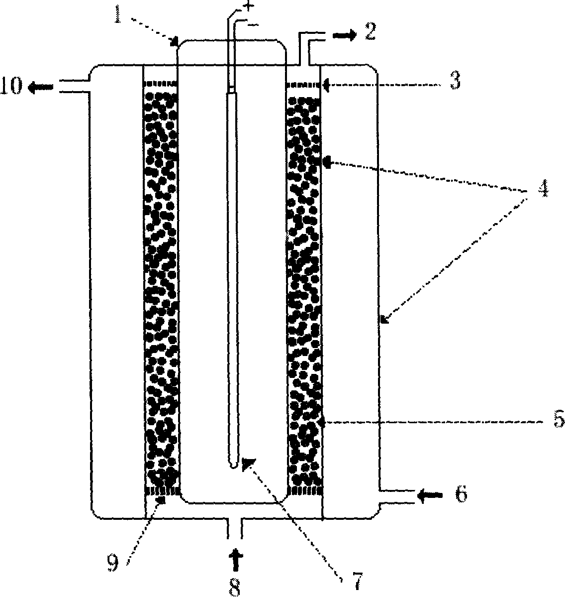
[0031] Such as figure 1 As shown, a purifying device for low-concentration organic pollutants in the air of the present invention is a continuous circulating fluidized bed photocatalytic reactor, which adopts a three-layer columnar glass reactor, and the innermost layer is a U-shaped quartz glass tube 1 , the outer layer and the middle layer are ordinary hard glass, the light source ultraviolet lamp 7 is placed coaxially in the U-shaped quartz glass tube 1, the interlayer between the outer layer and the middle layer is a cooling water jacket 4, and the U-shaped quartz glass tube 1 and the middle layer The space between is photocatalyst fluid bed layer 5, and the bottom of reactor has reaction gas inlet 8, and top has reaction gas outlet 2, and the bottom of reactor has cooling water inlet 6, and the top of reactor has cooling water outlet 10, in A porous sand core 9 is fixed on the bottom of the photocatalyst fluidized bed 5 to support the loaded photocatalyst, and a layer of ...
Embodiment 2
[0033] TiO 2 / SiO 2 The composite supported photocatalyst is prepared by the following method:
[0034] In the first step, butyl titanate was added dropwise to the vigorously stirred acetic acid solution to obtain a white slurry with a molar ratio of butyl titanate: acetic acid: water of 1:5:30, and continued stirring to obtain a transparent sol. After this sol continued to stir for 2 hours, a translucent gel solution was obtained;
[0035] In the second step, a certain amount of silica gel (treated with dilute nitric acid, washed with double distilled water, and dried at 120°C for 2 hours) was added to the above-mentioned translucent gel solution to impregnate the coating twice, each dipping the coating Finally, dry the silica gel at 70°C for 2 hours to obtain a photocatalyst precursor;
[0036] The third step is to calcinate the photocatalyst precursor at 450°C for 4 hours to obtain the TiO 2 / SiO 2 Supported photocatalyst (the loading amount of the catalyst is 15%, and...
Embodiment 3
[0038] TiO 2 / SiO 2 The composite supported photocatalyst is prepared by the following method:
[0039] In the first step, butyl titanate was added dropwise to the vigorously stirred acetic acid solution to obtain a white slurry with a molar ratio of butyl titanate: acetic acid: water of 1:10:40, and continued stirring to obtain a transparent sol. After this sol continued to stir for 3 hours, a translucent gel solution was obtained;
[0040] In the second step, a certain amount of silica gel (treated with dilute nitric acid, washed with double-distilled water, and dried at 120°C for 2 hours) was added to the above-mentioned translucent gel solution to impregnate the coating 5 times, each dipping the coating Finally, dry the silica gel at 80°C for 1.5 hours to obtain a photocatalyst precursor;
[0041] The third step is to calcinate the photocatalyst precursor at 300°C for 8 hours to obtain the TiO 2 / SiO 2 Supported photocatalyst (the loading amount of the catalyst is 10%...
PUM
 Abstract
Description
Claims
Application Information
 - R&D Engineer
- R&D Manager
- IP Professional
- Industry Leading Data Capabilities
- Powerful AI technology
- Patent DNA Extraction
Browse by: Latest US Patents, China's latest patents, Technical Efficacy Thesaurus, Application Domain, Technology Topic, Popular Technical Reports.
© 2024 PatSnap. All rights reserved.Legal|Privacy policy|Modern Slavery Act Transparency Statement|Sitemap|About US| Contact US: help@patsnap.com