


Quick Research
Generate reliable direction feasibility study reports for your R&D in just a few steps.

Technical Q&A
Discover and master advanced knowledge NOW. Basics, ideas, possibilities, all at once.

Find Solutions
As an expert in R&D theories, this can generate solutions to your technical problems instantly.

Evaluate Feasibility
Analyze your overall solution with one click, know your potential R&D risks in advance.

Monitor Landscape
Get weekly tech updates, stay abreast of the latest tech innovations and key insights.
Heating crucible and deposition apparatus including the same
A technology for deposition devices and crucibles, which is applied in lighting devices, ion implantation plating, coatings, etc., can solve the problem that the heating crucible does not have the repeatability of deposition rate, etc.
- Summary
- Abstract
- Description
- Claims
- Application Information
AI Technical Summary
Problems solved by technology
Method used
Image

Examples
Embodiment Construction
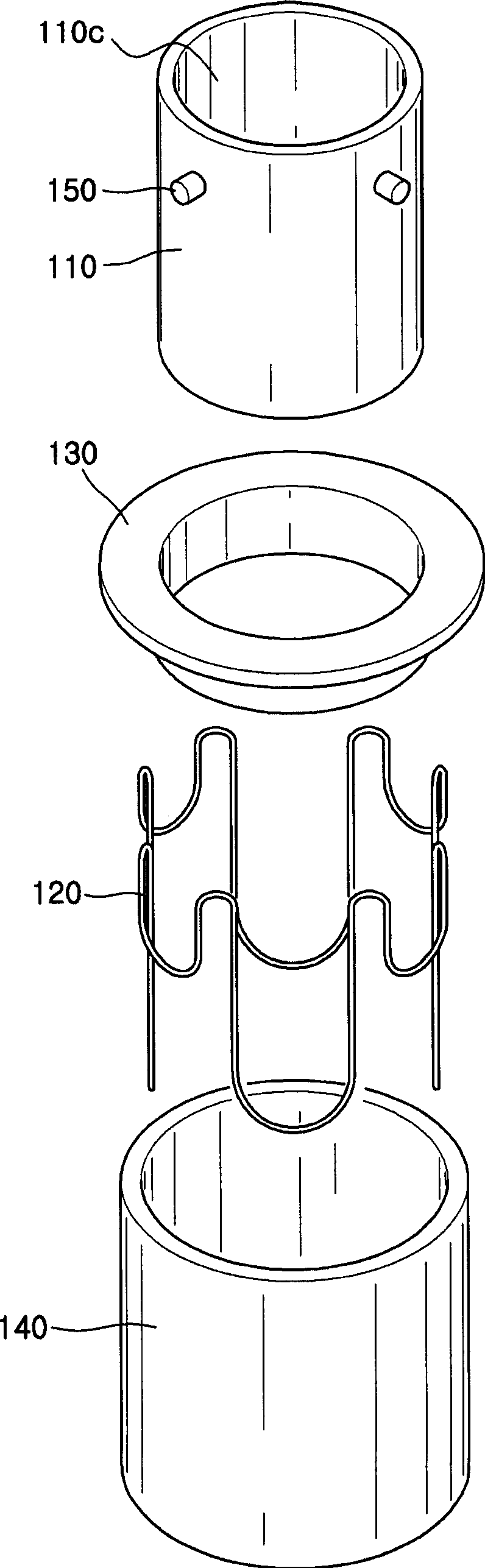
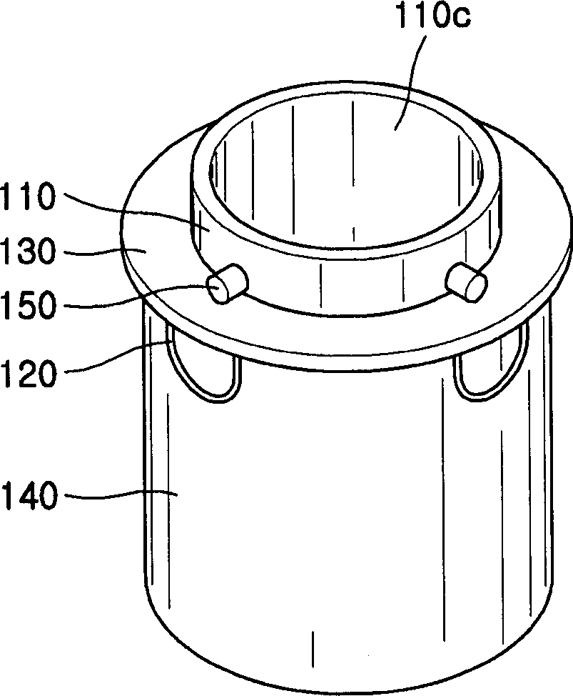
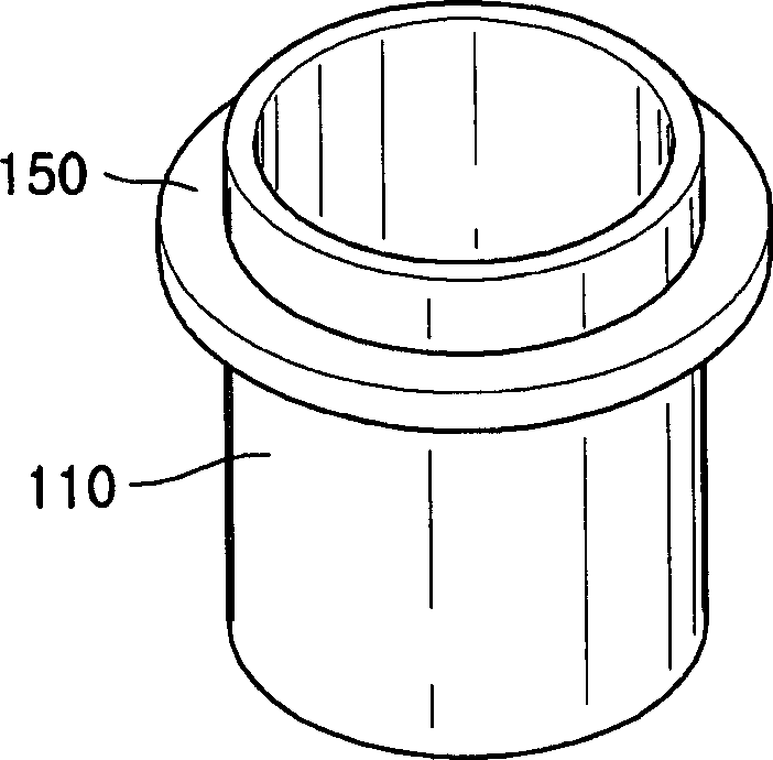
[0022] The heating crucible of the deposition device includes: a titanium body having an inner cavity and an opening, the inner cavity is used to accommodate the material to be deposited, and the opening is used to spray the material to be deposited; a wire is used to heat the main body; an insulator is used to Insulate the body from the wires. The invention also relates to a deposition device using the heated crucible in a deposition process.
[0023] Heating the crucible and deposition apparatus allows organic or metallic films to be deposited at a uniform deposition rate and with a high repetition rate of deposition. In addition, the organic film or metal film is deposited at a uniform deposition rate and excellent reproducibility, thereby enabling the display device to reproduce a uniform image across the entire screen.
[0024] The present invention is described more fully hereinafter with reference to the accompanying drawings that illustrate embodiments of the inventio...
PUM
 Abstract
Description
Claims
Application Information
 - R&D Engineer
- R&D Manager
- IP Professional
- Industry Leading Data Capabilities
- Powerful AI technology
- Patent DNA Extraction
Browse by: Latest US Patents, China's latest patents, Technical Efficacy Thesaurus, Application Domain, Technology Topic, Popular Technical Reports.
© 2024 PatSnap. All rights reserved.Legal|Privacy policy|Modern Slavery Act Transparency Statement|Sitemap|About US| Contact US: help@patsnap.com