Ball valve

A ball valve and ball valve technology, applied in valve devices, cocks including cut-off devices, engine components, etc., can solve problems such as damage to sealing parts and their adjacent parts, installation difficulties, etc., to achieve the effect of reducing space and compact structure

Inactive Publication Date: 2006-05-03
EFFEBI SPA
View PDF0 Cites 1 Cited by
  • Summary
  • Abstract
  • Description
  • Claims
  • Application Information

AI Technical Summary

Problems solved by technology

Therefore, the spherical valve plate whose diameter is only slightly larger than the diameter of the end portion of the inflow and outflow duct is constrained on the end portion of the duct by the aforementioned sealing member and its adjoining components, wherein said duct has a diameter intersecting the rotation axis of the valve plate. shaft, therefore, when subjected to an axial force from a member, there is a possibility that the valve plate may damage the sealing part and its adjacent parts
[0007] In addition, the provision of manual control elements, such as along A handle, butterfly handle, or lever set on a plane approximately perpendicular to the plane on which the valve body is located

Method used


Image

  • Ball valve
  • Ball valve
  • Ball valve

Examples


Embodiment Construction

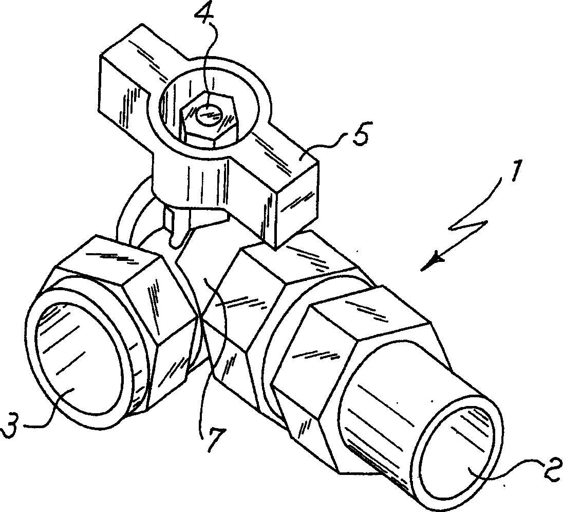
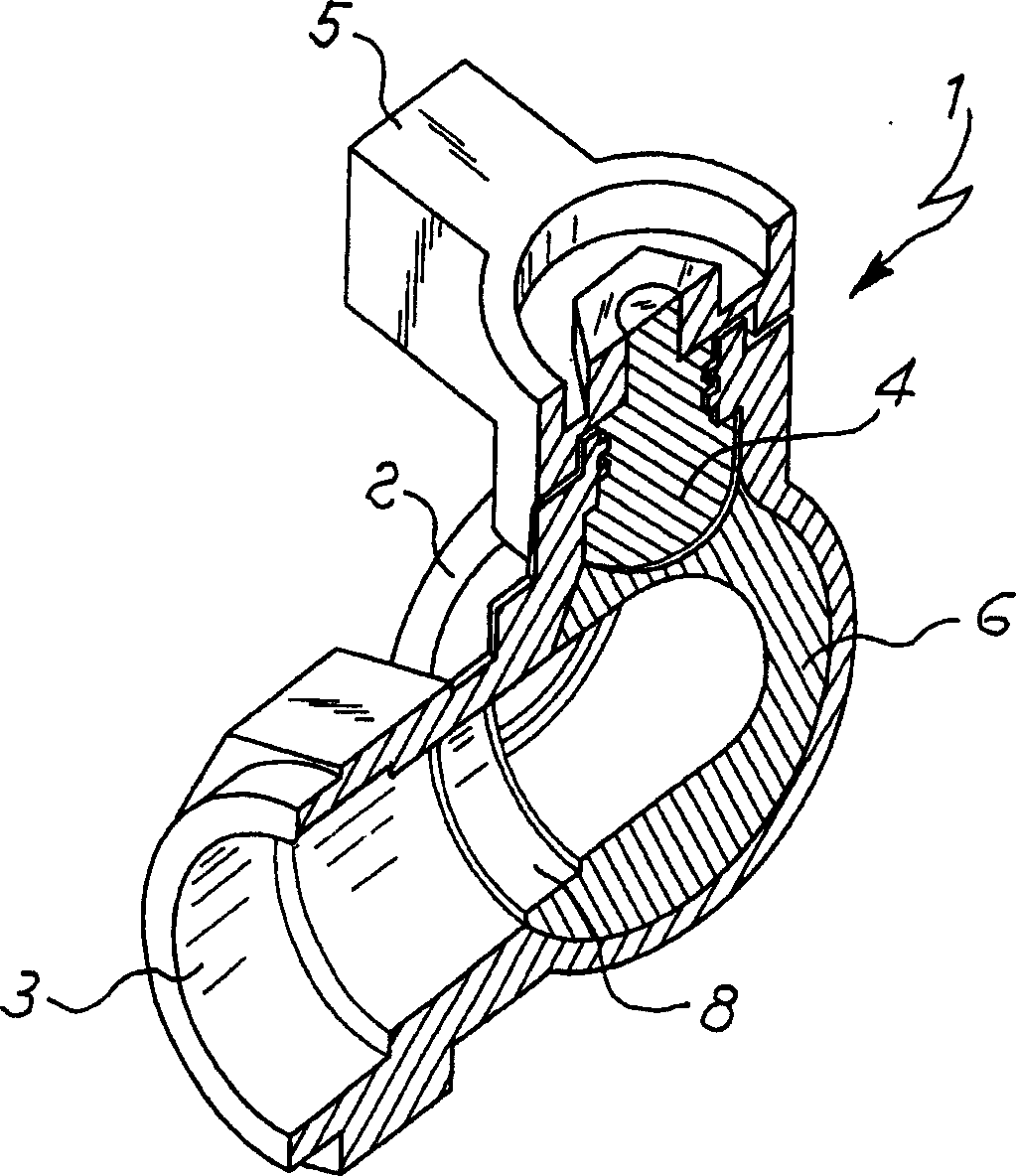
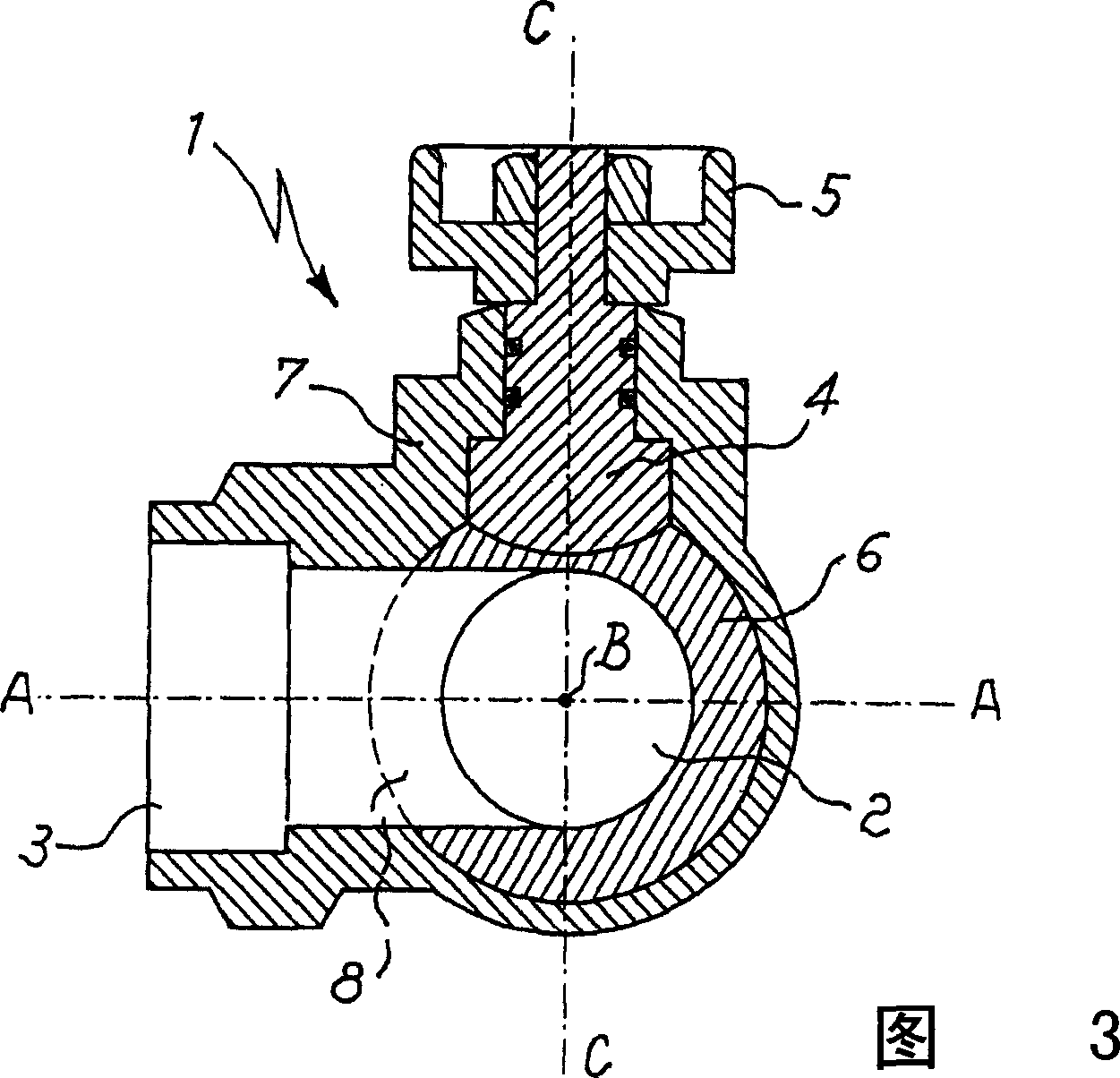
[0023] Referring to the above-mentioned drawings, the ball valve 1 of the present invention includes a cylindrical inflow pipe 2 having an axis B-B and a cylindrical outflow pipe 3 having an axis A-A. As shown, especially as Figure 4 As shown, the axis A-A of the outflow conduit 3 does not coincide with the axis B-B of the inflow conduit 2 . Especially in a particular form of embodiment of the invention as shown, the axis A A of the outflow duct 3 and the axis B-B of the inflow duct 2 intersect at a point (as Figure 4 As shown in C), thus defining the plane where the valve body 7 of the valve 1 is located.

[0024] In the particular embodiment of the invention shown, the axis A-A of the conduit 3 and the axis B-B of the conduit 2 are perpendicular to each other so that the fluid flowing through the valve 1 is deflected by 90 degrees when flowing from the outlet conduit 2 to the outlet conduit 3 .

[0025] However, alternative embodiments of the ball valve in the claimed te...


PUM


Abstract

A ball valve (1), comprising at least one fluid inflow pipe (2) and at least one fluid outflow pipe (3), the axes (BB: AA) of the inflow and outflow pipes do not coincide, and at least one Rotating spherical valve plate (6) is used to cut / regulate the flow rate of fluid from the inflow pipe to the outflow pipe. Advantageously, the axis of rotation (CC) of said at least one spherical valve plate substantially intersects the axis (A-A) of said outflow duct (3) and the axis (BB) of said inflow duct (2) .

Description

technical field [0001] The invention relates to a ball valve, in which two pipelines have non-coincident shafts, and the two pipelines are separated or achieve corresponding fluid communication through a rotating spherical valve plate. Background technique [0002] The embodiment of ball valve (or faucet) is known technology, in the ball valve, the axes of the inflow and outflow pipelines of fluid are preferably perpendicular to each other, and are set to intersect each other at one point, or at least in a non-overlapping manner, so that the fluid can be changed in The direction of flow inside the valve while defining a plane in which the valve body generally lies. In these embodiments, the rotating spherical valve plate is positioned corresponding to the area where the two pipes are connected, and its axis of rotation intersects the axis of one of the inflow and outflow pipes. A sealing ring is usually placed between the spherical valve plate and the end portion of the con...

Claims


Application Information

Patent Timeline
Patent Type & Authority Applications(China)
IPC IPC(8): F16K5/06
CPCF16K5/061
Inventor E·汤赫蒂
Owner EFFEBI SPA
Why Eureka
Try Eureka