
Laterally triggered musical instrument switch pressing assembly and musical instrument control switch

A technology for controlling switches and switches, applied in electrical switches, electrical components, circuits, etc., can solve problems such as shell deformation, reducing the distance between pressing components and pressing switches, and distance changes

Active Publication Date: 2021-01-01
长沙幻音电子科技有限公司
View PDF3 Cites 0 Cited by
  • Summary
  • Abstract
  • Description
  • Claims
  • Application Information

AI Technical Summary

Problems solved by technology

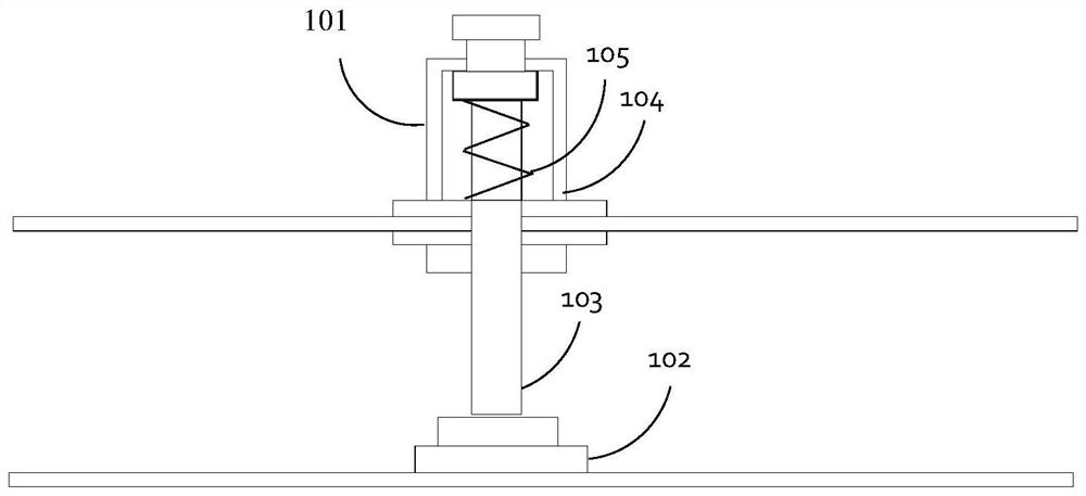
However, there are many factors that affect the actual results in actual engineering applications. For example, the length of the pressing shaft may be different due to manufacturing tolerances, and assembly errors may cause the distance between the push switch and the push component to change. Or the rigidity limit of the device's shell will cause the shell to deform when the user exerts too much force, reducing the distance between the pressing component and the push switch
Therefore, the instrument control switch shown in Figure 1 is hard to avoid There is a problem that the actual maximum moving distance of the pressing axis is greater than the design required distance

Method used


Image

  • Laterally triggered musical instrument switch pressing assembly and musical instrument control switch
  • Laterally triggered musical instrument switch pressing assembly and musical instrument control switch
  • Laterally triggered musical instrument switch pressing assembly and musical instrument control switch

Examples


Embodiment Construction

[0023] In order to make the purpose, technical solution and advantages of the present application clearer, the present application will be further described in detail below in conjunction with the accompanying drawings and embodiments. It should be understood that the specific embodiments described here are only used to explain the present application, and are not intended to limit the present application.

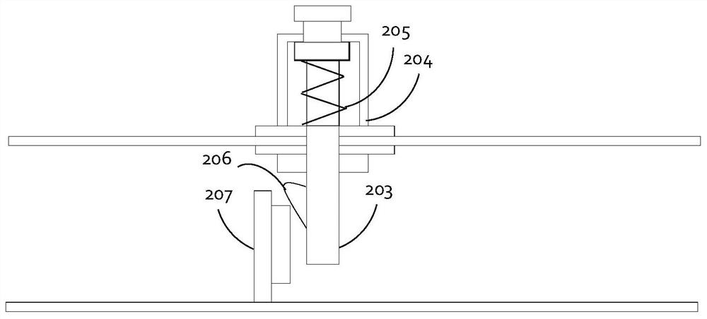
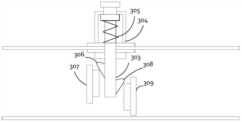
[0024] In one embodiment, such as figure 2 As shown, a side-triggered musical instrument switch pressing assembly is provided, including a housing 204 , an elastic reset mechanism 205 and a pressing shaft 203 . The pressing shaft 203 is disposed through the housing 204 through the through hole, and can move relative to the housing 204 along the travel direction of the pressing assembly. The casing 204 also includes an elastic return mechanism realized by a spring 205 . One end of the spring 205 is connected to the pressing shaft 203, and the other end is connected to th...


PUM


Abstract

The invention relates to a laterally triggered musical instrument switch pressing assembly, a musical instrument control switch and a musical instrument control device. The musical instrument switch pressing assembly comprises a shell, an elastic reset mechanism and a pressing shaft, the pressing shaft penetrates through the shell through a through hole, one end of the pressing shaft is a pressingend, the other end of the pressing shaft is a triggering end, the elastic reset mechanism is arranged in the shell, and the pressing shaft can move relative to the shell from the initial position inthe stroke direction of the musical instrument switch pressing assembly. The surface of the trigger end is provided with a projection in a direction perpendicular to the stroke direction of the musical instrument switch pressing assembly. When the musical instrument switch pressing assembly is used, the pressing type switch can be arranged according to the shape of the protrusion and the stroke distance of the pressing type switch, so that the protrusion extrudes the pressing type switch in the moving process to be switched on, and excessive pressure on the pressing type switch due to excessive pressing force of a user is avoided; permanent deformation of an elastic mechanism in the push-type switch is avoided, and the service life of the musical instrument control switch can be prolonged.

Description

technical field [0001] The present application relates to the technical field of musical instrument control equipment, in particular to a side-triggered musical instrument switch pressing assembly and a musical instrument control switch. Background technique [0002] When playing a musical instrument, users often use switches to control the device. For example, a guitar effector needs to use a foot-operated control switch to trigger the corresponding function. [0003] like figure 1 As shown, the current push-type musical instrument control switch generally includes a housing 104 , a push shaft 103 , a return spring 105 and a push-type switch 102 . The casing 104 , the pressing shaft 103 and the return spring 105 form a retractable pressing assembly 101 . The casing 104 is generally fixed on the casing of the control device or musical instrument through structures such as screws and nuts. The push switch 102 is arranged on the opposite side of one top of the pressing shaf...

Claims


Application Information

Patent Timeline
IPC IPC(8): H01H13/14H01H13/20H01H13/02
CPCH01H13/14H01H13/20H01H13/02
Inventor 刘杰
Owner 长沙幻音电子科技有限公司
Learn More