Eureka AIR delivers breakthrough ideas for toughest innovation challenges, trusted by R&D personnel around the world.

Centralized water discharge apparatus and method for tunnelling

A tunnel engineering and tunnel technology, which is applied in safety devices, drainage, earthwork drilling and mining, etc., can solve the problems of deteriorating construction operation environment, water seepage, water leakage, etc., and achieve the effect of simple construction, high efficiency and low production cost

Inactive Publication Date: 2006-05-03
CHANGAN UNIV
View PDF0 Cites 28 Cited by
  • Summary
  • Abstract
  • Description
  • Claims
  • Application Information

AI Technical Summary

Problems solved by technology

Moreover, in water-rich areas, large-scale water seepage, water leakage and even water gushing occurred during the construction of the tunnel project, which deteriorated the construction environment.
[0006] There are many reasons for the leakage of tunnel engineering. One of the main reasons is that when the water content of the surrounding rock is high, a large amount of groundwater seeps out from the initial support and cannot be quickly introduced into the drainage pipe through the waterproof and drainage layer. Build up with the waterproof and drainage layer to form a large water pressure. Because of the continuous accumulation of water pressure and the existing waterproof and drainage methods, it is impossible to be comprehensive and leak-proof during construction.

Method used


Image

  • Centralized water discharge apparatus and method for tunnelling
  • Centralized water discharge apparatus and method for tunnelling
  • Centralized water discharge apparatus and method for tunnelling

Examples


Embodiment 1

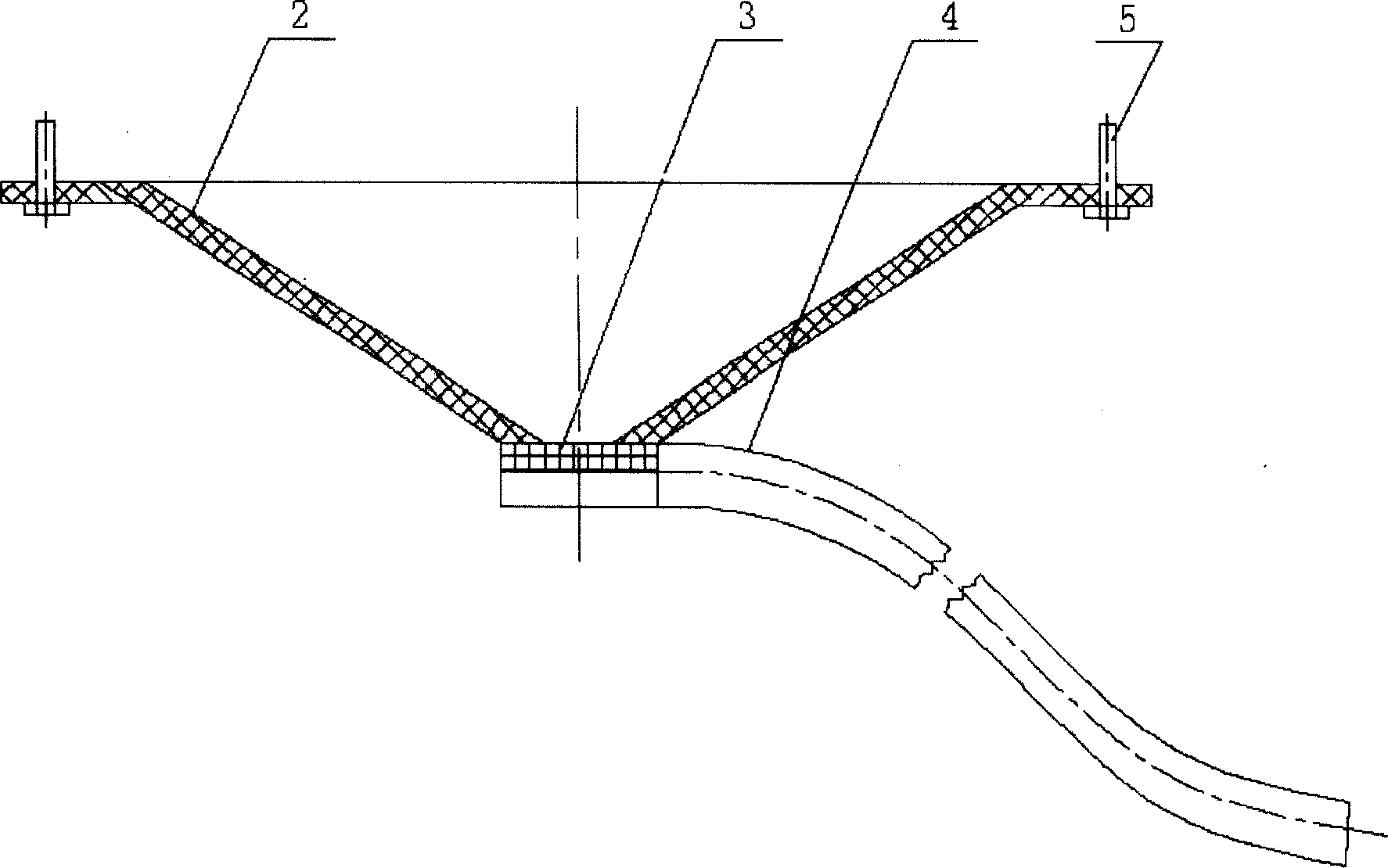
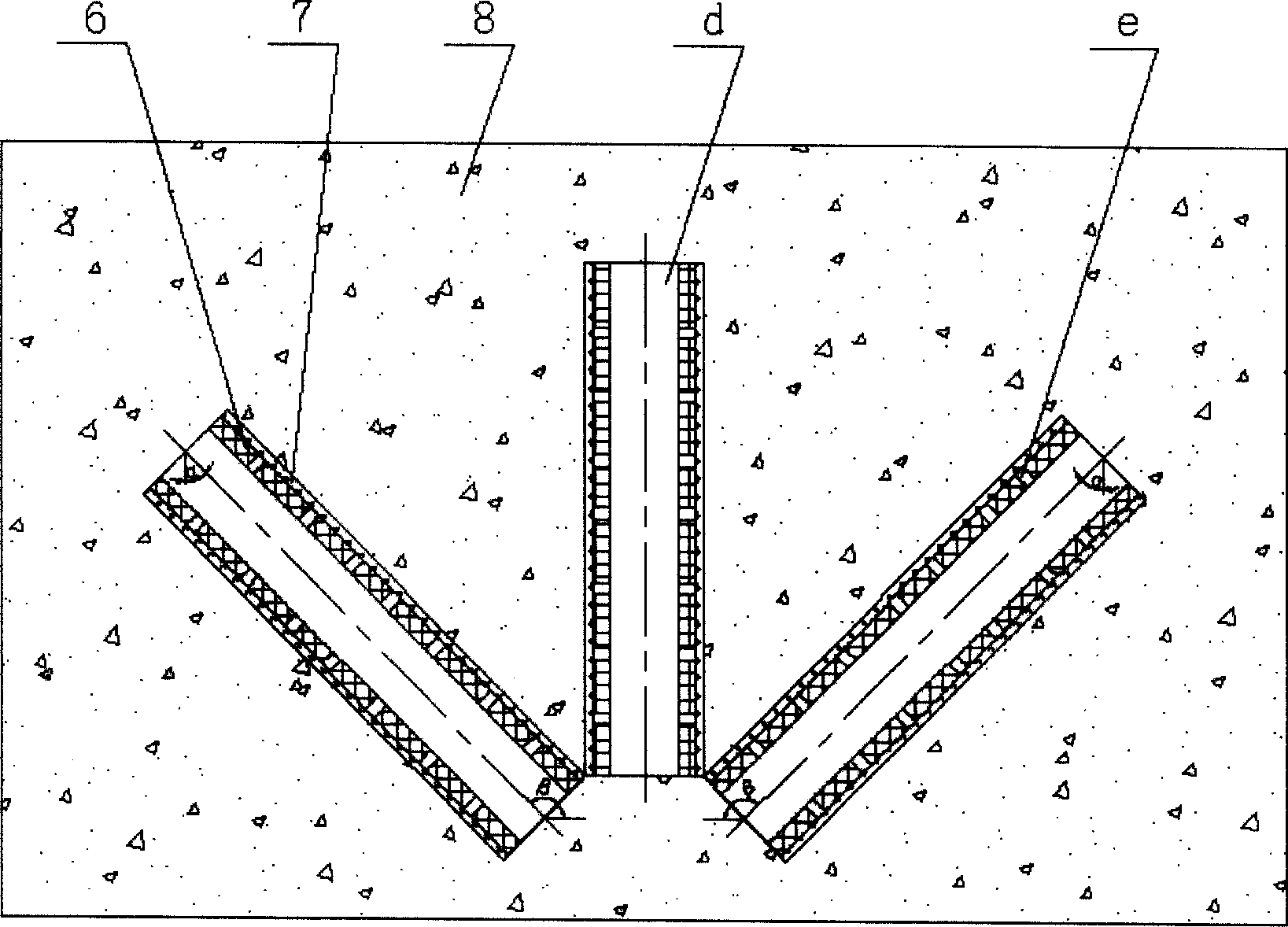
[0027] exist figure 1 , 2 , 3, the centralized drainage device of the tunnel engineering of the present embodiment is made of funnel 2, filter screen 3, drainpipe 4, expansion bolt 5, diversion pipe 6, filter cloth 7. In the initial support 1 in the tunnel and in the water diversion hole d of the water seepage concentrated part of the tunnel surrounding rock 8, the water diversion pipe 6 is installed. The water diversion pipe 6 of the present embodiment is a polyvinyl chloride pipe, a nylon pipe, or a stainless steel pipe can also be used. The radial processing of the water diversion pipe 6 has a water seepage hole e, and the water leaked from the surrounding rock of the tunnel 8 can enter the water diversion pipe 6 from the water seepage hole e, and wrap the non-woven fabric outside the water diversion pipe 6, and the non-woven fabric is the filter cloth 7 An embodiment, also available nylon or plastics gauze, filter cloth 7 is used for preventing silt from clogging the seep...

Embodiment 2

[0036] In this embodiment, the shape of the funnel 2 is a quadrangular prism whose upper base is larger than the lower base. The shape of the funnel 2 can also be a triangular prism with the upper bottom larger than the lower bottom, or a hexagonal prism with the upper bottom larger than the lower bottom, or a pentagonal truss or other prisms with the upper bottom larger than the lower bottom. . Other components and the coupling relationship of the components are the same as in Embodiment 1.

Embodiment 3

[0038] In this embodiment, three water diversion holes d in different orientations and different directions converging at one point are drilled in the primary support 1 and the tunnel surrounding rock 8 where seepage is concentrated. The angle α is 30°, the angle β between the centerline of the water diversion hole and the horizontal plane is 135°, and the three water diversion holes d are evenly arranged on the same cone surface. The depth of the water diversion hole d is 2m, and the diameter of the water diversion hole d is 10cm. The centralized drainage device of the tunnel engineering used is the same as that of Embodiment 1.


PUM


Abstract

The invention discloses a concentrated drainage device and method of tunnel engineering, which comprises the following parts: water diversion pipe, filter layer on the outside of water diversion pipe, funnel under the initial support water diversion pipe, screen under the funnel and drainage pipe under the screen, wherein the water diversion pipe is set in the water diversion hole d of tunnel adjacent bed creepage centralization part. The method comprises the following steps: drilling the water diversion hole d in the tunnel initial support and tunnel adjacent bed creepage centralization part; leveling the initial support surface; setting the concentrated drainage device in the tunnel engineering.

Description

technical field [0001] The invention belongs to the technical field of waterproofing and drainage of highway tunnels, and in particular relates to a centralized drainage device and method for tunnel engineering. Background technique [0002] For many years, the impact and harm of water on tunnel engineering has been a problem that has been widely concerned but has not been well resolved. The harm of water to tunnel engineering is multifaceted, including: the erosion of groundwater can cause erosion and damage to the lining structure, thereby endangering the durability of the lining structure; the repeated freezing and thawing cycles of leaking water in severe cold areas cause the freezing and thawing of the lining concrete. If the water freezes on the road surface, it will deteriorate the driving environment and endanger driving safety. Moreover, the ice nodules and ice plugs formed by the freezing of leaking water will invade the tunnel clearance or block the drainage chann...

Claims


Application Information

Patent Timeline
Patent Type & Authority Applications(China)
IPC IPC(8): E21F16/02
Inventor 叶飞
Owner CHANGAN UNIV
Why Eureka
Eureka Blog
Learn More