Turbulent flow spray nozzle

A technology of turbulent nozzles and nozzles, applied in the direction of spraying devices, spraying devices, etc., can solve the problems of high viscosity of coatings and paints, affect the quality of spraying, and affect the progress of work, so as to achieve large spraying work area, improve construction quality, and improve uniformity degree of effect

Inactive Publication Date: 2006-05-03
黄修文
View PDF1 Cites 4 Cited by
  • Summary
  • Abstract
  • Description
  • Claims
  • Application Information

AI Technical Summary

Problems solved by technology

But the existing nozzles that are used for spraying coatings are all single-hole high-pressure nozzles. As described in Chinese patent CN03810784. Therefore, only a single performance paint can be sprayed. When it is necessary to spray paints of different varieties and properties, or to spray different effects, it is necessary to replace another specification of turbulent flow nozzles. Therefore, one spray gun needs to be equipped with multiple nozzles, so that Equipment is more expensive
Moreover, due to the high viscosity of the paint or paint, a large delivery pressure is required during spraying, which often causes the paint to be sprayed from the nozzle too fast, resulting in paint splashing, which not only affects the spraying quality, but also causes paint waste.
On the other hand, the paint is mostly a mixture of multiple components. When it reaches the nozzle through a long conveying path, it may separate and cause the color of the paint to change. If it is sprayed like this, the wall after spraying will definitely Unexpected colors and effects
Furthermore, the viscosity of paint and paint is relatively high, and the nozzle will be blocked after a period of use, while the traditional nozzle cleaning takes a lot of time and affects the work progress

Method used


Image

  • Turbulent flow spray nozzle
  • Turbulent flow spray nozzle
  • Turbulent flow spray nozzle

Examples


Embodiment Construction

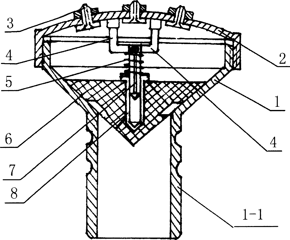
[0016] exist figure 1 In the embodiment, the cavity of the nozzle main body 1 is in the shape of a trumpet with a small inlet and a big outlet, and the bottom of the inlet is connected with a connecting straight pipe 1-1, and the outer wall of the connecting straight pipe 1-1 is formed with a ring-shaped groove, which is beneficial to other nozzles. The machine tool is clamped, and the outlet end of the nozzle main body 1 is connected with the nozzle end cover 2 in a threaded manner. There are many through holes distributed on the end cover 2 of the nozzle, and the nozzle 3 with a stop passes through the through hole on it from the bottom of the end cover 2 of the nozzle, and the nut is screwed into the thread of the exposed nozzle 3 and tightened, and the nozzle 3 is fastened On the nozzle end cover 2, the nozzles 3 can be nozzles with different nozzle sizes.

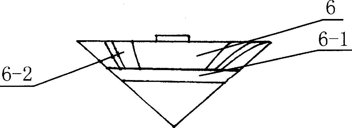
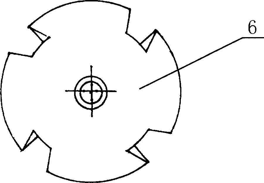
[0017] The trumpet-shaped cavity of the nozzle main body 1 is equipped with a cone 6 that matches it. The cone cone...


PUM


Abstract

The invention discloses a turbulent current injector for plating which is characterized in that the cavity in horn shape of main body has a matched cone, while in the function of jacking device, the cone is peaked on the surface of said cavity, and the cone top is embedded into the inlet; the side surface of cone has a inclined groove whose one end in the bottom of cone and through to the parallel annular groove or the parallel spiral groove, while a sealed ring is arranged in the annular groove. When the paint with pressure peaks the cone, the turbulent current valve is through; the paint into inclined groove or spiral groove can generate the rotational moment to rotate the cone which can mix the paint; the function of turbulent current valve is to reduce the high pressure of paint in the working condition to make the paint sprayed more uniformly. Each injector on the end cap of turbulent current injector is in the single detachable structure which can be detached for washing easily and change into different size injector according to demand.

Description

(1) Technical field: [0001] The invention relates to a spray head, in particular to a turbulent flow spray head. (two) background technology: [0002] The interior walls of traditional houses are painted with lime or white putty. In order to achieve the moisture-proof and anti-corrosion of the walls, facilitate cleaning and increase personalization, it is popular to use paint or paint to decorate the walls, which can not only Improve the quality of the wall, but also by spraying different colors of paint or paint to make the wall present a colorful state. But the existing nozzles that are used for spraying coatings are all single-hole high-pressure nozzles. As described in Chinese patent CN03810784. Therefore, only a single performance paint can be sprayed. When it is necessary to spray paints of different varieties and properties, or to spray different effects, it is necessary to replace another specification of turbulent flow nozzles. Therefore, one spray gun needs to be ...

Claims


Application Information

Patent Timeline
Patent Type & Authority Applications(China)
IPC IPC(8): B05B1/34
Inventor 黄修文
Owner 黄修文
Why Eureka
Try Eureka