Shield cable
A shielded cable, a new technology
- Summary
- Abstract
- Description
- Claims
- Application Information
AI Technical Summary
Problems solved by technology
Method used
Image
Examples
Embodiment 1
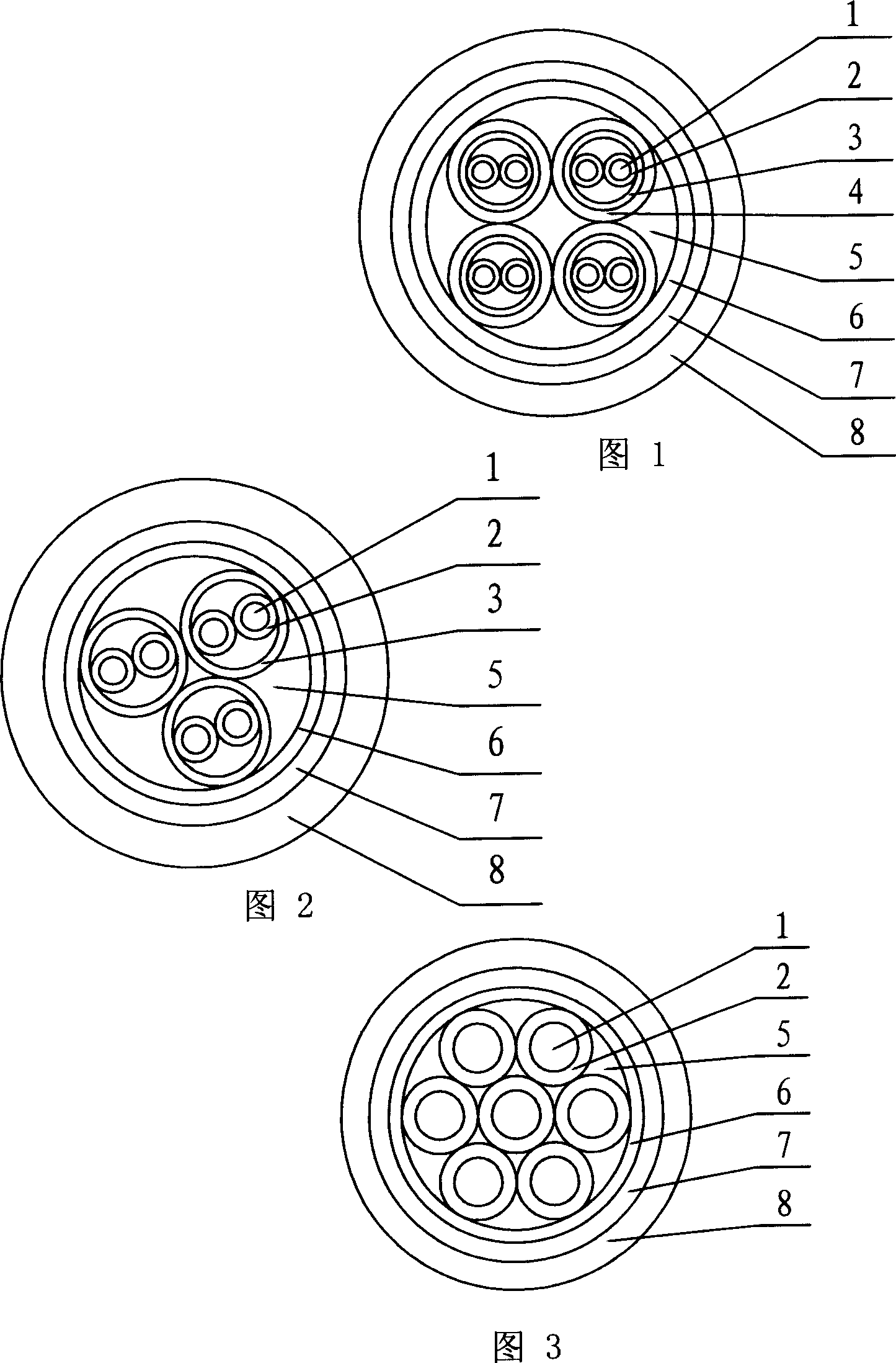
[0013] As shown in Figure 1, the outer surface of the oxygen-free copper wire as the conductor 1 is extruded with a polyvinyl chloride (or polyethylene, cross-linked polyethylene) insulation layer 2 to form an insulated core, and two insulated cores are twisted into a pair. For the twisted wire group, the polyester tape wrapping layer 3 and the braided copper-clad aluminum or copper-clad aluminum alloy wire sub-shielding layer 4 are wound on the twisted wire group. The twisted pair with tape layer 3 and sub-shield layer 4 is used to form a cable, and at the same time, PP filling rope or non-alkali glass filling rope is used as filler 5, and polyester tape tape layer 6 is wrapped around it. Copper-clad aluminum or copper-clad aluminum alloy wire overall shielding layer 7 is braided on the belt layer 6, and an outer sheath 8 of polyvinyl chloride or halogen-free low-smoke flame-retardant polyolefin is extruded on the overall shielding layer 7.
Embodiment 2
[0015] As shown in Figure 2, the outer surface of the conductor 1 is made of oxygen-free copper wire, and the insulating layer 2 of polyvinyl chloride (or polyethylene, cross-linked polyethylene) is extruded to form an insulated core, and two insulated cores are twisted into a pair. For the twisted wire group, wrap the polyester tape wrapping layer 3 on the twisted wire group. The twisted pair with the tape layer 3 is used to form a cable, and at the same time, the filler 5 is filled with PP filling rope or alkali-free glass filling rope, and the polyester tape is wrapped around the tape layer 6 . Copper-clad aluminum or copper-clad aluminum alloy wire overall shielding layer 7 is braided on the belt layer 6, and an outer sheath 8 of polyvinyl chloride or halogen-free low-smoke flame-retardant polyolefin is extruded on the overall shielding layer 7.
Embodiment 3
[0017] As shown in Figure 3, the outer surface of the oxygen-free copper wire as the conductor 1 is extruded with a polyvinyl chloride (or polyethylene, cross-linked polyethylene) insulating layer 2 to form an insulated core, and multiple insulated cores are directly cabled. , and at the same time use PP filling rope or non-alkali glass filling rope as filler 5 to fill, and wrap polyester tape wrapping layer 6 around. Copper-clad aluminum or copper-clad aluminum alloy wire overall shielding layer 7 is braided on the belt layer 6, and an outer sheath 8 of polyvinyl chloride or halogen-free low-smoke flame-retardant polyolefin is extruded on the overall shielding layer 7.
PUM
 Abstract
Description
Claims
Application Information
 - R&D
- Intellectual Property
- Life Sciences
- Materials
- Tech Scout
- Unparalleled Data Quality
- Higher Quality Content
- 60% Fewer Hallucinations
Browse by: Latest US Patents, China's latest patents, Technical Efficacy Thesaurus, Application Domain, Technology Topic, Popular Technical Reports.
© 2025 PatSnap. All rights reserved.Legal|Privacy policy|Modern Slavery Act Transparency Statement|Sitemap|About US| Contact US: help@patsnap.com

