SECAM color difference signal processing method

A digital video and color-difference signal technology, applied in color signal processing circuits, by changing the field conversion of the input video signal, the direction of the TV, etc., can solve the problem of difficult to see the image, and achieve the effect of stabilizing the image data

Inactive Publication Date: 2006-04-05
OKI ELECTRIC IND CO LTD
View PDF2 Cites 0 Cited by
  • Summary
  • Abstract
  • Description
  • Claims
  • Application Information

AI Technical Summary

Problems solved by technology

As shown in Figure 10, in this case, the data of n+4 lines and n+317 lines change with a period of 2 fields, and the image is difficult to see clearly due to this periodic color change

Method used


Image

  • SECAM color difference signal processing method
  • SECAM color difference signal processing method
  • SECAM color difference signal processing method

Examples


no. 1 Embodiment approach

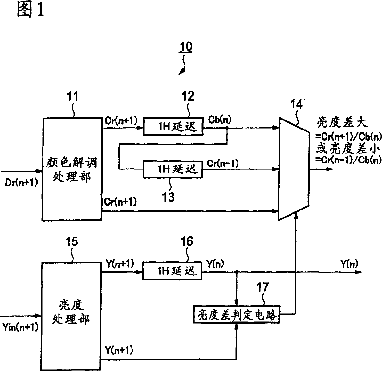
[0030] 1 is a block diagram showing the configuration of a color difference data processing circuit according to the first embodiment of the present invention. The processing circuit 10 includes a color demodulation processing unit 11, a first delay circuit 12, a second delay circuit 13, a selector 14, A luminance processing unit 15 , a third delay circuit 16 , and a luminance difference determination circuit 17 .

[0031] The color demodulation processing unit 11 receives the red color difference data Dr(n+1) of the SECAM method (n is the number of the scanning line), and generates a demodulated color signal Cr(n+1). This color signal Cr(n+1) is input to the first delay circuit 12 simultaneously with the input to the selector 14, and as its output, a blue color signal Cb(n) one line ahead is obtained. This color signal Cb(n) is input to the second delay circuit 13 simultaneously with the input to the selector 14, and as its output, a red color signal Cr(n-1) one line earlier ...

no. 2 Embodiment approach

[0036] 2 is a block diagram showing the configuration of a color difference data processing circuit according to a second embodiment of the present invention. The processing circuit 20 includes a color demodulation processing unit 21, a first delay circuit 22, a second delay circuit 23, a selector 24, A luminance processing unit 25 , a third delay circuit 26 , a luminance difference determination circuit 27 , and an averaging circuit 28 .


PUM


Abstract

The invention relates to a method for processing the color difference of an SECAM digital video frequency decoder. In order to obtain stable image data from the SECAM digital video frequency decoder, the processing method comprises the following steps: a first delay unit (12), leading a color signal Cr (n+1) demodulated by means of a color demodulation signal of an SECAM way to delay 1H so as to obtain the color signal Cb (n); a second delay unit (13), leading the color signal Cb (n) to further delay the 1H so as to obtain the color signal Cr (n-1); a third delay unit(16), leading brightness data Y (n+1) to delay the 1H so as to obtain a brightness signal Y (n); brightness difference decision unit (17), comparing and delaying the brightness signal Y (n) and the Y (n+1), outputting the signal corresponding to the brightness difference, and choosing and outputting two random signals of the Cr (n+1), the Cb (n) and the Cr (n-1) according to the signal corresponding to the brightness difference.

Description

technical field [0001] The invention relates to a video signal processing in SECAM mode, in particular to the color difference signal processing of a SECAM digital video decoder. Background technique [0002] The digital video decoder is used to demodulate the digitally sampled image signal and transform it into YcbCr or RBG digital data. [0003] There are signals based on NTSC, PAL, SECAM, etc. among video signals, and the present invention relates to SECAM signal processing. Fig. 3 shows the overall structure of the existing digital video decoder. The digital video decoder 30 is composed of an analog-to-digital conversion unit (ADC) 31 , a synchronization processing unit 32 , a Y / C separation unit 33 , a brightness processing unit 34 , a color demodulation processing unit 35 , and a data format processing unit 36 ​​. [0004] After an analog video input signal is input to the ADC ( 31 ), the analog signal is converted into a digital signal and output to the Y / C separati...

Claims


Application Information

Patent Timeline
Patent Type & Authority Applications(China)
IPC IPC(8): H04N9/64
CPCH04N7/012H04N7/0132H04N9/64
Inventor 冈本康彦
Owner OKI ELECTRIC IND CO LTD
Why Eureka
Try Eureka