Organic electroluminescent device and its method of manufacture

A technology of electroluminescent devices and organic light-emitting layers, which is applied in the direction of electroluminescent light sources, semiconductor/solid-state device manufacturing, and electric solid-state devices, and can solve problems such as leakage current, interruption, and short circuit

Active Publication Date: 2013-05-22
SAMSUNG DISPLAY CO LTD
View PDF0 Cites 0 Cited by
  • Summary
  • Abstract
  • Description
  • Claims
  • Application Information

AI Technical Summary

Problems solved by technology

Therefore, when the cathode electrode 32 contacts the HTL 21, there is a possibility of causing leakage current
In addition, when the cathode electrode 32 contacts the anode electrode 12, a short circuit is caused
In addition, when the dispersion method is used to form HTL21 and organic EML 20R, 20G and 20B, the problem of interruption of HTL 21 or organic EML 20R, 20G and 20B occurs

Method used


Image

  • Organic electroluminescent device and its method of manufacture
  • Organic electroluminescent device and its method of manufacture
  • Organic electroluminescent device and its method of manufacture

Examples


Embodiment Construction

[0024] The present invention will now be described more fully with reference to the accompanying drawings, in which exemplary embodiments of the invention are shown. In the drawings, like reference numbers indicate like elements, and the thicknesses of layers and regions are exaggerated for clarity.

[0025] image 3 is a plan view of an organic electroluminescent device according to an embodiment of the present invention, Figure 4 It is a cross-sectional view taken along line IV-IV' in Fig. 3 . Figure 5 is a perspective view of banks and partitions of an organic electroluminescence device according to an embodiment of the present invention.

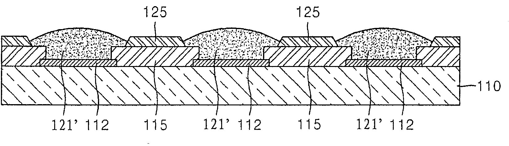
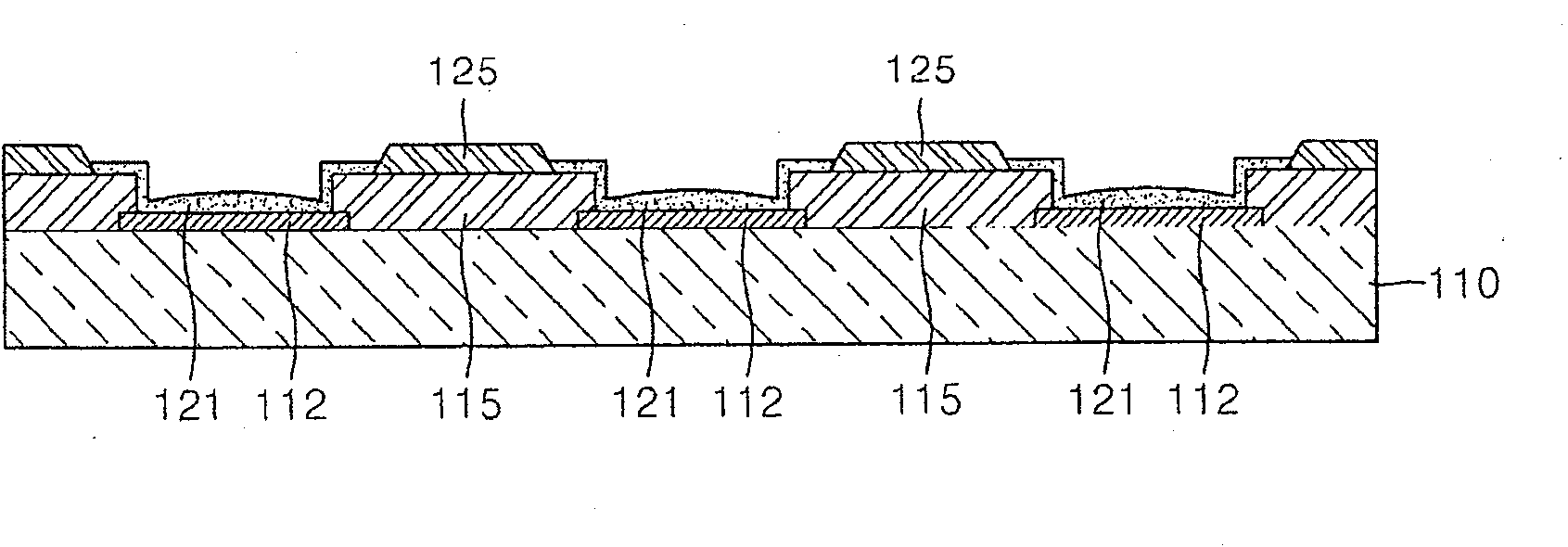
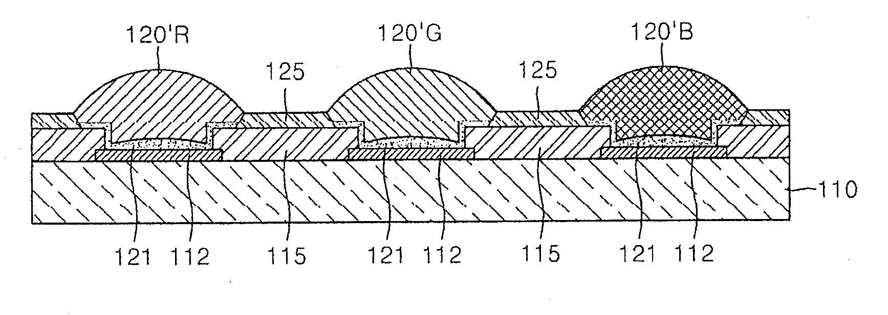
[0026] refer to Figures 3 to 5 , a plurality of first electrodes 112 are formed in stripes on the substrate 110 . Substrate 110 may typically be a glass substrate or a plastic substrate. The first electrode 112 may be an anode electrode. In a bottom emission type organic electroluminescence device, the first electrode 112 may be...


PUM


Abstract

An organic electroluminescent device includes: a substrate; a plurality of first electrodes arranged on the substrate; a plurality of banks arranged on the substrate and the first electrodes to define pixels on the first electrodes, the plurality of banks being of an inorganic material; a plurality of separators arranged in stripe shapes on the plurality of banks between the pixels, the plurality of separators being of an organic material; organic Emitting Material Layers (organic EMLs), each having a predetermined color, the organic EMLs being arranged within each of the pixels; and a plurality of second electrodes arranged on the organic EMLs, the plurality of banks, and the plurality of separators.

Description

technical field [0001] The present invention relates to an organic electroluminescent device and a manufacturing method thereof, and more particularly, to an organic electroluminescent device capable of preventing leakage current, short circuit and color mixing between pixels and a manufacturing method thereof. Background technique [0002] Generally, an organic electroluminescence device realizes image display by utilizing light emitted by the recombination of holes provided by an anode electrode and electrons provided by a cathode electrode in an organic light-emitting material layer formed between the anode electrode and the cathode electrode. device. Due to superior display characteristics such as wide viewing angle, fast response time, low manufacturing cost, and high contrast ratio, organic electroluminescent devices are expected to be next-generation flat panel display devices. [0003] Organic electroluminescence devices can be classified into passive matrix (PM) ty...

Claims


Application Information

Patent Timeline
Patent Type & Authority Patents(China)
IPC IPC(8): H01L27/32H01L21/82H01L51/50H01L51/56
CPCH01L27/3283H01L51/0005H01L27/3211H10K59/35H10K59/173H10K71/135H05B33/22H05B33/26H05B33/10
Inventor 李晟熏朴俊勇金相烈黄亿采
Owner SAMSUNG DISPLAY CO LTD
Why Eureka
Try Eureka