Waste gas purifying apparatus

A technology of exhaust gas purification device and catalyst, which is applied in the direction of exhaust device, noise reduction device, engine components, etc. It can solve the problems of impossible precise adjustment and limited degree of freedom, and achieve easy output adjustment, improved degree of freedom, accuracy and high efficiency Adjustment effect

Inactive Publication Date: 2006-04-05
HONDA MOTOR CO LTD
View PDF1 Cites 4 Cited by
  • Summary
  • Abstract
  • Description
  • Claims
  • Application Information

AI Technical Summary

Problems solved by technology

[0006] However, in the case where the target output of the engine is to be obtained, the output characteristics are adjusted by this leakage hole. However, in the prior art, since the location of the leakage hole is limited, it is impossible to perform precise adjustment, so the output characteristics are mostly determined. Due to the length of the exhaust pipe, the design freedom is limited
[0007] In addition, as in the prior art figure 1 As shown, if the catalyst is arranged in the center of the muffler, it is difficult to say that the purification performance is the best. In addition, as Figure 4 As shown, if the leak hole is opened in the chamber on the downstream side of the muffler with multiple chambers, other noise reduction measures need to be taken

Method used


Image

  • Waste gas purifying apparatus
  • Waste gas purifying apparatus
  • Waste gas purifying apparatus

Examples


Embodiment Construction

[0031] Hereinafter, embodiments of the present invention will be described with reference to the drawings. In addition, "front", "rear", "left", "right", "up", and "down" are directions seen from the driver's point of view, Fr indicates the front side, Rr indicates the rear side, and L indicates the left side side, R means the right side. Furthermore, the drawings should be viewed in the direction of the reference numerals.

[0032] figure 1 It is a left side view showing an example of a motorcycle using the present invention.

[0033] Next, the schematic structure of a two-wheeled motor vehicle will be described using this figure.

[0034] Automatic two-wheel vehicle 210 is a kind of small automatic two-wheel vehicle, and it is mainly made of following parts: vehicle frame 211; Front fork 212 that is installed on the head pipe 211a of vehicle frame 211; ; the handle 214 that is connected on the front fork 212; the power unit 215 that is installed in the rear portion of th...


PUM


Abstract

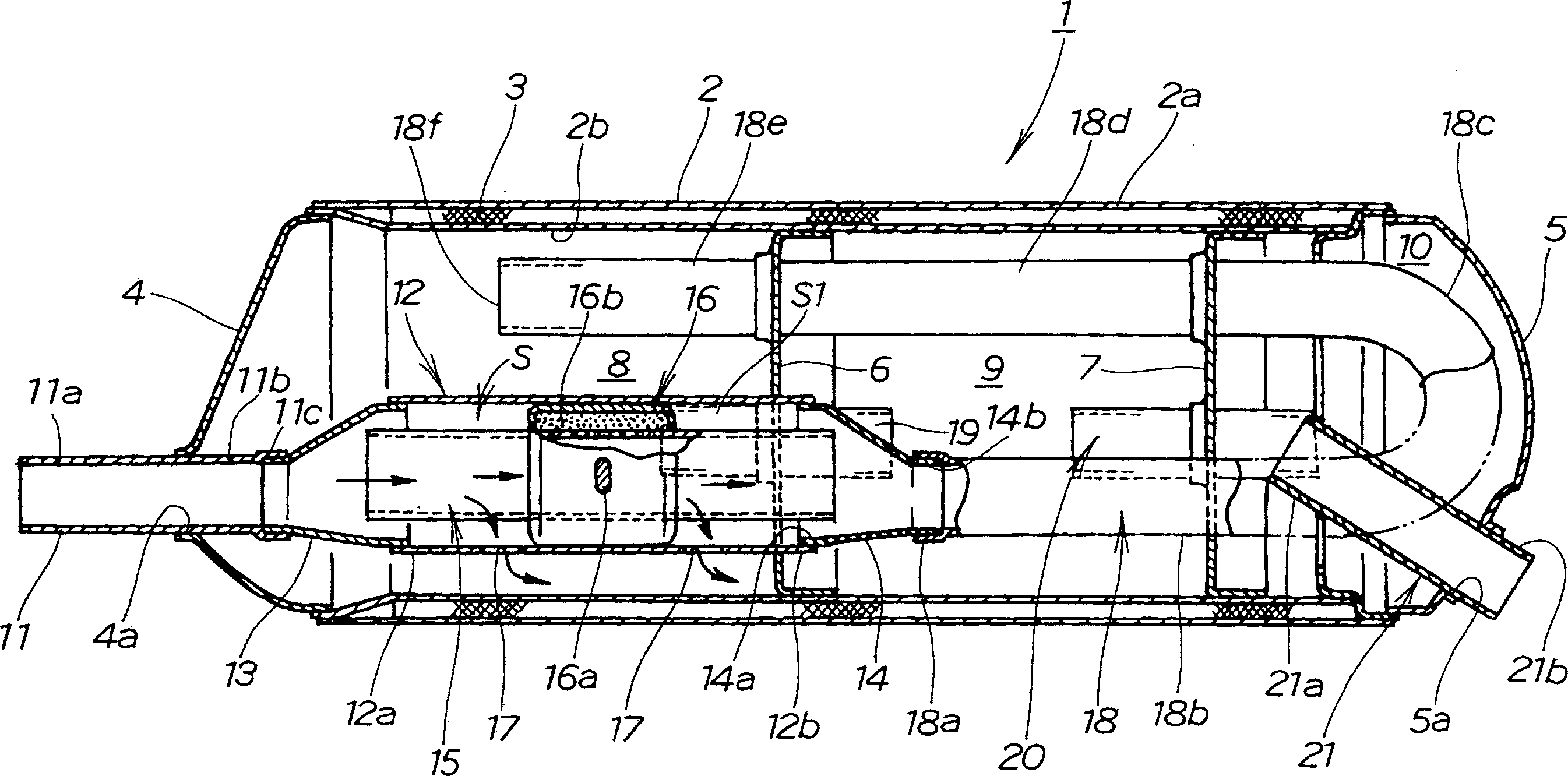
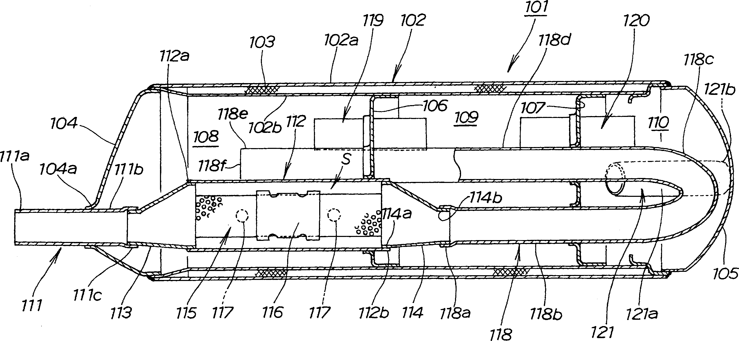
The invention provides a waste gas cleaning plant, which is formed by accommodating and allocating a catalyst tube-shaped body formed by a tube-shaped body in a muffler, and is used to adjust the output of a motor without depending only on the pipe length, and also improve the gas exhausting effect and the performance. The waste gas cleaning plant is formed by accommodating the catalyst tube-shaped body formed by a perforated plate which is attached with catalyst in the muffler having a plurality of expansion chambers; wherein, the catalyst tube-shaped body (15) is allocated in an expansion chamber (8) at the uppermost stream of an exhaust stream, namely allocating the catalyst tube-shaped body (15) in the expansion chamber (8) which is nearest to a connecting pipe (11) connected with an exhaust pipe at the flank of the motor, an outer cylinder is used for coating the periphery of the catalyst tube-shaped body (15), tap holes which are isolated with a certain distance along the posteroanterior direction and are overlapped with the catalyst tube-shaped body along the posteroanterior direction are arranged on the outer cylinder, and a part of waste gas which passes the circumference of the catalyst tube-shaped body is leaked to the expansion chambers through the tap holes.

Description

technical field [0001] The present invention relates to an exhaust gas (exhaust gas) purification device installed in a muffler. Background technique [0002] Conventionally, there is known an exhaust gas purifying device in which a cylindrical body including a catalyst-attached punched metal plate or the like is accommodated in a muffler (for example, refer to Patent Document 1). [0003] Patent Document 1: JP-A-2004-150310 [0004] The technology disclosed in the above-mentioned bulletin, just as the bulletin figure 1 As shown, the exhaust device E of the internal combustion engine (using the symbols in this publication, the same below) has an exhaust gas (exhaust gas) purification device 3, and the exhaust gas purification device is arranged between the first exhaust pipe 1 and the second exhaust pipe 2, and has a catalyst part 30 arranged in the exhaust muffler 4, and the exhaust gas purification device 3 has an outlet part 34 for forming an outlet passage 36 through w...

Claims


Application Information

Patent Timeline
Patent Type & Authority Applications(China)
IPC IPC(8): F01N3/24F01N1/08F01N3/28
CPCF01N3/2882F01N2230/04F01N2590/04
Inventor 前田哲明五十岚和则
Owner HONDA MOTOR CO LTD
Why Eureka
Try Eureka