Received signal strength measurement circuit, received signal strength detection circuit and wireless receiver

A technology for receiving signal strength and measuring circuits. It is applied to improve amplifiers to reduce temperature/power supply voltage changes, electrical components, and transmission systems. It can solve problems such as output characteristic dependence, error, and change, and achieve improved communication characteristics and improved reception. The effect of precision

Inactive Publication Date: 2006-03-15
SHARP KK
View PDF1 Cites 12 Cited by
  • Summary
  • Abstract
  • Description
  • Claims
  • Application Information

AI Technical Summary

Problems solved by technology

[0014] In this way, there is a problem in the conventional RSSI circuit system: because the temperature dependence of the output amplitude (gain) varies greatly with the input level to the intermediate frequency amplifier circuit 1220 Similarly, output characteristics vary depending on temperature, which can be a major cause of error
[0015] In the above-mentioned prior art, there are still the following problems: In order to improve the temperature dependence of this output, the conversion circuit 1240 is required, so that the entire circuit is composed of numerous and diverse; the RSSI circuit When the system is built into the LSI, it is also necessary to incorporate the occupied area for the conversion circuit 1240, which hinders the miniaturization and high integration of the circuit; the conversion circuit 1240 increases the current consumption

Method used


Image

  • Received signal strength measurement circuit, received signal strength detection circuit and wireless receiver
  • Received signal strength measurement circuit, received signal strength detection circuit and wireless receiver
  • Received signal strength measurement circuit, received signal strength detection circuit and wireless receiver

Examples


Embodiment approach 1

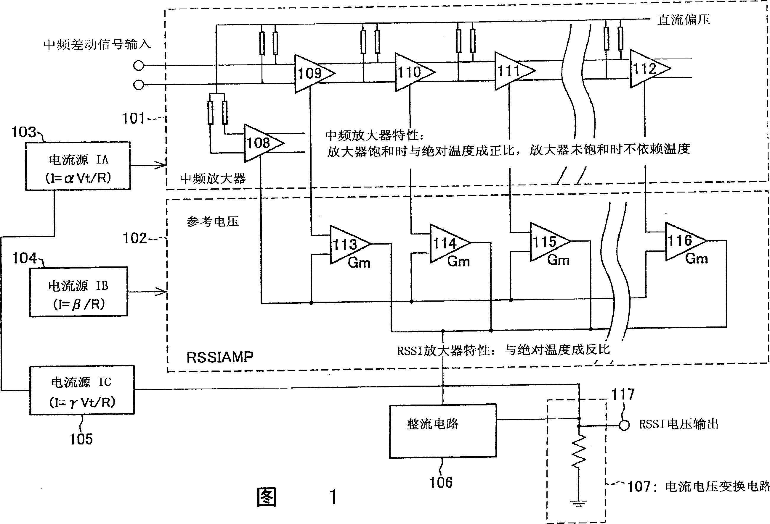
[0041]Hereinafter, embodiments of the present invention will be described in detail with reference to the drawings. FIG. 1 is an embodiment showing the outline of the RSSI circuit of the present invention. The RSSI circuit includes an intermediate frequency amplifier 101 , an RSSI amplifier (voltage-current conversion unit) 102 , a current source IA 103 , a current source IB 104 , a current source IC 105 , a rectifier circuit 106 , and a current-voltage conversion unit (voltage output unit) 107 .

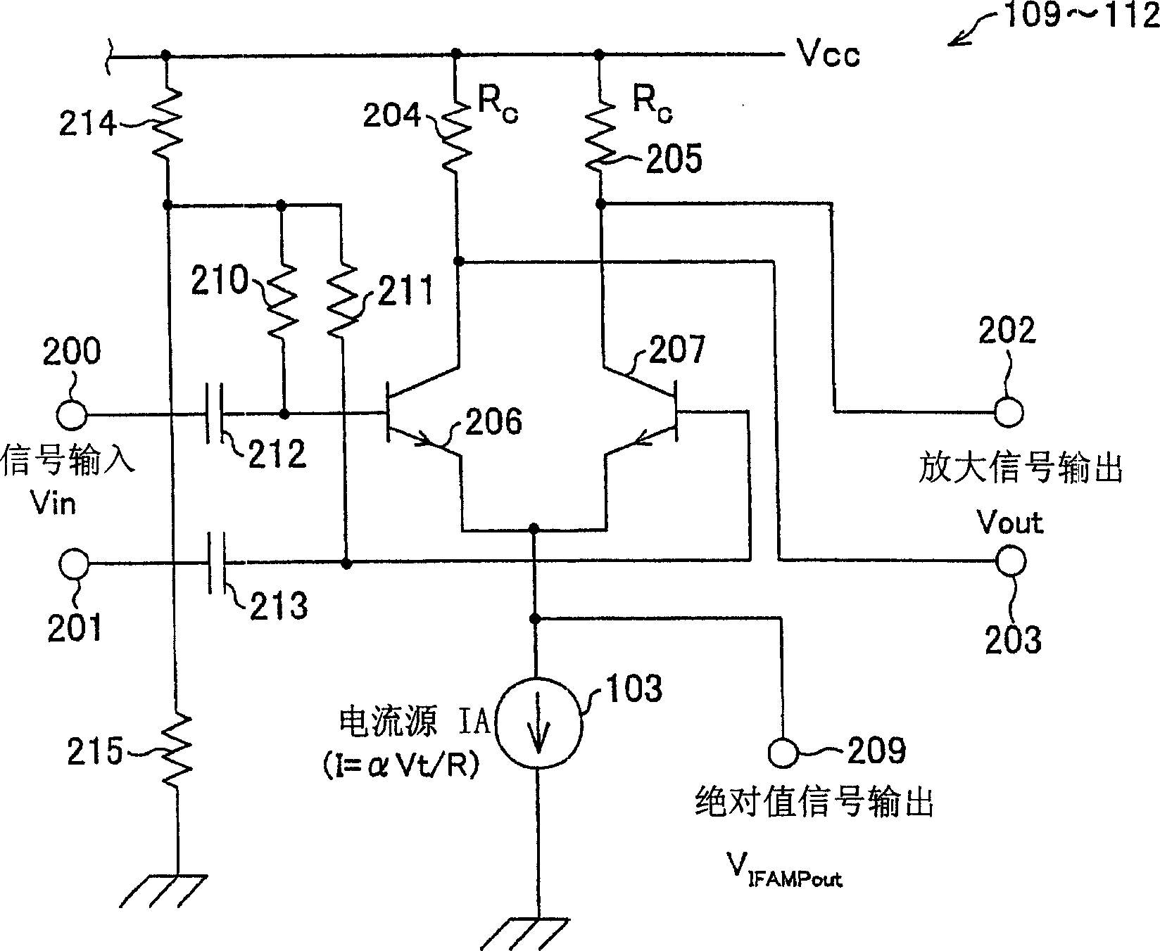
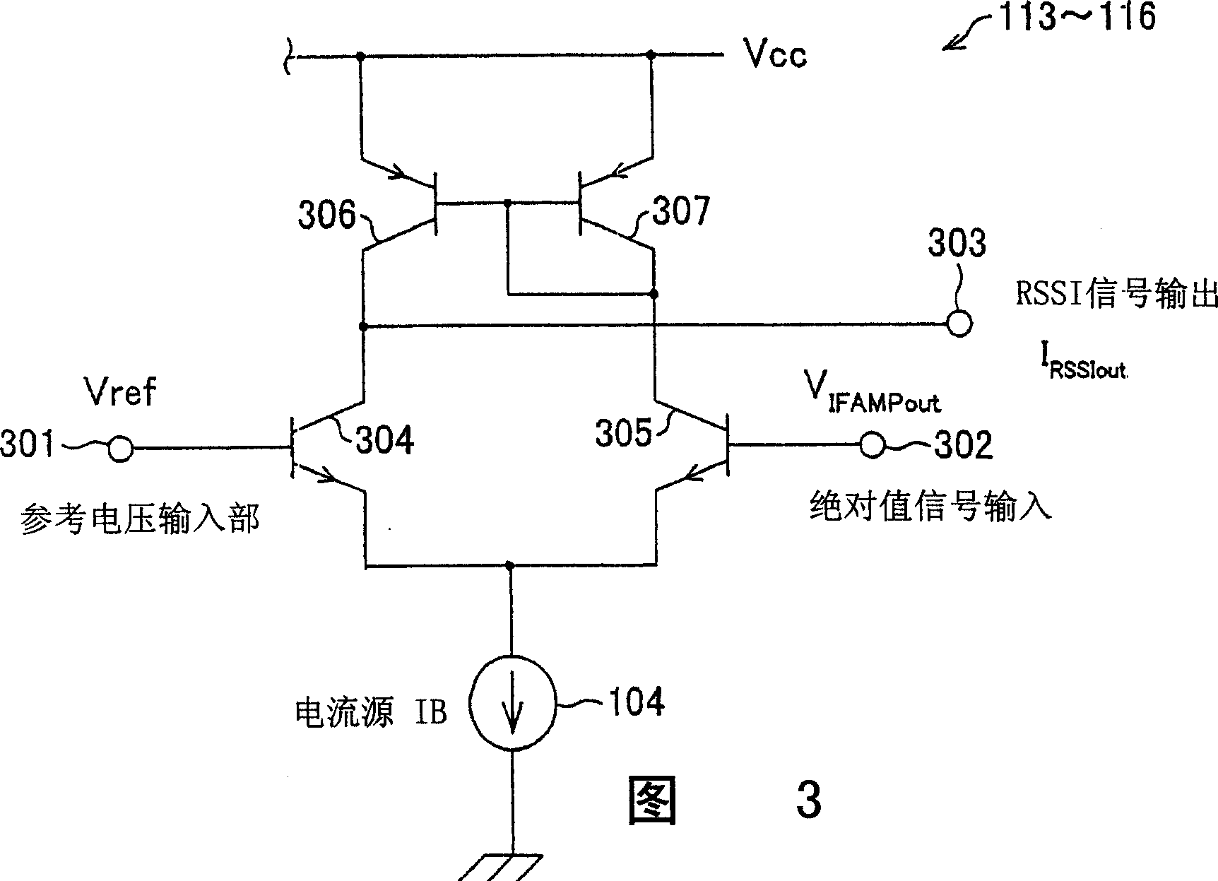
[0042] An intermediate frequency amplifier is formed by cascading multi-stage amplifiers (differential amplifiers) 109-112. The stages of amplifiers 109 to 112 constituting the intermediate frequency amplifier amplify the input signal, and sequentially output the amplified output to the subsequent amplifier.

[0043] In addition to the function of amplification, the amplifiers 109-112 also have the function of respectively outputting absolute value signals whose magnitude is propor...


PUM


Abstract

The RSSI circuit of the present invention includes: an IF amplifier section, which includes multiple stages of serially connected differential amplifiers for amplifying, with use of a current source IA provided as a power source for amplification, an IF signal corresponding to a received signal; an RSSI amplifier section for converting into current a voltage amplitude of an absolute value signal outputted from the differential amplifiers of the IF amplifier section, using a current source IB provided as a power source for conversion, and adding and outputting the converted current; and a current voltage conversion circuit for converting into voltage the output current from the RSSI amplifier section, and outputting the converted voltage as a measurement voltage value. The RSSI amplifier section is set so that a current value of the RSSI amplifier section is inversely proportional to absolute temperature. With the configuration, it is possible to realize an RSSI circuit, a received signal strength detection circuit and a wireless receiver, which are able to stabilize a strength measurement of a received signal relative to a change in temperature and to increase communication characteristics.

Description

technical field [0001] The present invention relates to a received signal strength measuring circuit (generally referred to as an RSSI circuit), a received signal strength detecting circuit, and a wireless receiver using the same, which are used in a wireless receiving device and have excellent temperature stability. Background technique [0002] In a wireless receiver, generally, a high-frequency wireless signal obtained from an antenna is first converted into an intermediate frequency signal (IF signal), and then the intermediate frequency signal is amplified and input to a detector. Desired processing, that is, detection processing for extracting information contained in the wireless signal is performed in the detector. In this detection process, the amplification factors of the wireless signal and the intermediate frequency signal are set in accordance with the signal strength of the radio wave received by the wireless receiver so as to be within a range suitable for per...

Claims


Application Information

Patent Timeline
Patent Type & Authority Applications(China)
IPC IPC(8): H04B17/00H04B1/16H03F1/30H03F3/45H03F3/68H04B1/26
CPCH04B17/318H04B17/0057G01N27/12
Inventor 中野佳明
Owner SHARP KK
Why Eureka
Try Eureka