
Discharge lamp of the short arc type

A discharge lamp and short arc technology, applied in the direction of discharge lamps, gas discharge lamps, high pressure discharge lamps, etc., can solve the problems of high cost and easy disconnection, and achieve the effect of preventing falling off and simple installation.

Active Publication Date: 2006-03-15
USHIO DENKI KK
View PDF2 Cites 0 Cited by
  • Summary
  • Abstract
  • Description
  • Claims
  • Application Information

AI Technical Summary

Problems solved by technology

For example, although platinum is suitable as a high temperature resistant spring material, it is expensive and has disadvantages such as easy disconnection.

Method used


Image

  • Discharge lamp of the short arc type
  • Discharge lamp of the short arc type
  • Discharge lamp of the short arc type

Examples


Embodiment Construction

[0027] use Figure 1 to Figure 3 The first embodiment of the present invention will be described.

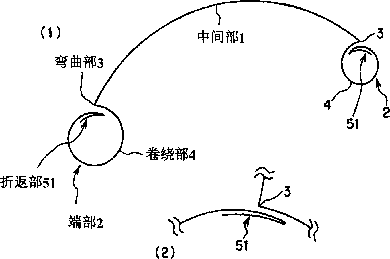
[0028] figure 1 (1) is a diagram showing the structure of the trigger wire fixed to the short-arc discharge lamp in the invention of the present embodiment, figure 1 (2) is figure 1 An enlarged view of the vicinity of the bent portion 3 and the folded portion 51 shown in (1).

[0029] In these figures, 1 is the middle part of the arc-shaped trigger wire arranged along the outer surface of the arc tube of the short-arc discharge lamp; 2 is the end of the trigger wire fixed to the sealing tube of the short-arc discharge lamp; 3 is a bent portion formed between the middle portion 1 and the end portion 2; 4 is a winding portion wound around the sealing pipe portion in the end portion 2; 51 is a folded back at the front end portion of the end portion 2 into a substantially V-shape department.

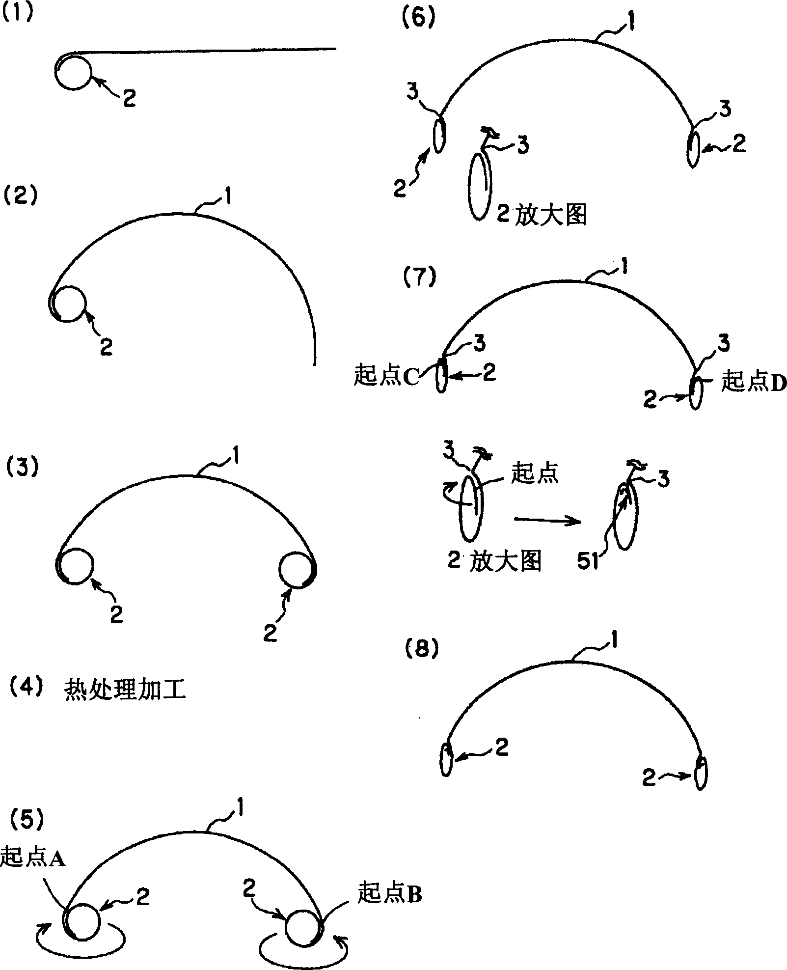
[0030] figure 2 yes means figure 1 (1) Fabrication process of the trigger wire sho...


PUM


Abstract

A discharge lamp of the short arc type which has an arc tube in which there is a pair of opposed electrodes, a pair of hermetically sealing parts which extend outward from opposite ends of the arc tube, and a trigger wire, each end of which is wound around one of the hermetically sealing parts, with a middle area of the trigger wire running along the outside surface of the arc tube. In the area of at least one of the ends of the trigger wire, a bend is formed which comes to rest on one of the hermetically sealing parts, and following this bend, a fold is formed at the outer end area of the end of the trigger wire.

Description

technical field [0001] The present invention relates to a short-arc discharge lamp containing xenon gas used as a light source for a projector, or a short-arc discharge lamp containing mercury used as a light source for semiconductor exposure, for example. Background technique [0002] For short-arc discharge lamps, trigger wires are usually arranged on the outer surface of the luminous tube in order to reduce the breakdown voltage. [0003] In Japanese Patent Laid-Open No. 51-78586, as a method of fixing the trigger wire to the lamp, it is disclosed that the trigger wire is wound once in a sealed tube connected to both ends of the luminous tube, and the trigger wire is twisted and rotated once with a tool. End-to-end technology. [0004] In addition, JP-A-2002-367566 discloses the following technique of processing elastic metal wires such as stainless steel into a bow shape in accordance with the shape of the arc tube, and springs matching the diameter of the sealing tube ...

Claims


Application Information

Patent Timeline
Patent Type & Authority Applications(China)
IPC IPC(8): H01J61/54
CPCH01J61/544H01J61/86H01J61/54
Inventor 山本真由美神山浩
Owner USHIO DENKI KK
Learn More