Eureka AIR delivers breakthrough ideas for toughest innovation challenges, trusted by R&D personnel around the world.

System and method for automatically transferring a defect image from an inspection system to a database

A technology of inspection system and database, applied in the field of lithography, can solve the problems of reducing money and wasting time, and achieve the effect of reducing operator errors

Inactive Publication Date: 2006-03-08
TOPPAN PHOTOMASKS INC
View PDF0 Cites 0 Cited by
  • Summary
  • Abstract
  • Description
  • Claims
  • Application Information

AI Technical Summary

Problems solved by technology

This labor-intensive process wastes time and money and can reduce photomask fab productivity

Method used


Image

  • System and method for automatically transferring a defect image from an inspection system to a database
  • System and method for automatically transferring a defect image from an inspection system to a database
  • System and method for automatically transferring a defect image from an inspection system to a database

Examples


Embodiment Construction

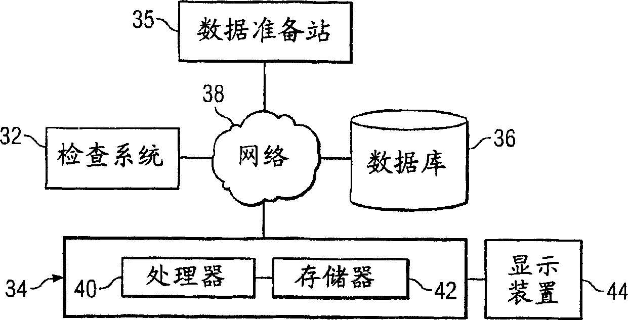
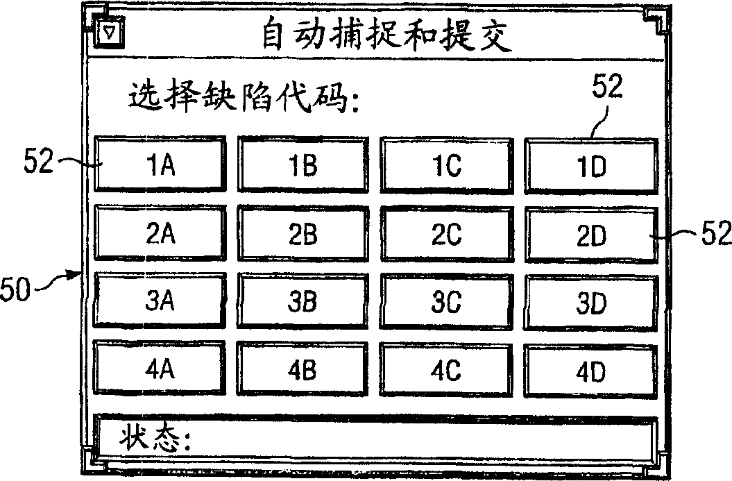
[0019] by reference Figure 1 to Figure 4 , the preferred embodiment of the present invention and its advantages can be understood to the greatest extent, and the same numerals in the figures are used to denote the same or corresponding parts.

[0020] figure 1 Shown is a cross-sectional view of a photomask assembly 10 that may be inspected by automatically transferring defect images from an inspection system to a database. Photomask assembly 10 includes photomask 12 coupled to pellicle assembly 14 . Substrate 16 and patterned layer 18 cooperate to form part of photomask 12 . Photomask 12 may also be described as a mask or reticle, which may have a variety of sizes and shapes including, but not limited to, generally circular, circular, rectangular, or square. The photomask 12 can also be any kind of photomask type, including but not limited to, a disposable master, a 5 inch reticle, a 6 inch reticle, a 9 inch reticle, or one that can be used to project an image of a circuit...


PUM


Abstract

A system and method for automatically transferring a defect image from an inspection system to a database are disclosed. The method includes identifying a defect on a lithography component loaded into an inspection system and capturing an image of the identified defect. An operator is prompted to select a defect code for the identified defect and the captured image is automatically transferred to a database in response to the operator selecting the defect code.

Description

[0001] related application [0002] This application claims U.S. Provisional Patent Application Serial No. 60 / 428,110, filed November 21, 2002, by Roy Eric Staveley, entitled "Method for Automatically Transferring an Image of a Defecton a Photomask from an Inspection System to a Database" rights and interests. technical field [0003] The present invention relates generally to lithography, and more particularly to systems and methods for transferring defect images from an inspection system to a database. Background technique [0004] As semiconductor manufacturers continue to make smaller devices, the requirements for the photomasks used to make these devices continue to become more stringent. A photomask, also known as a reticle or mask, generally includes a substrate on one surface of which a non-transmissive or partially transmissive layer is formed. The non-transmissive or partially transmissive layer typically includes patterns representing images that can be transfer...

Claims


Application Information

Patent Timeline
Patent Type & Authority Applications(China)
IPC IPC(8): G06F17/30G03F1/84G06K9/00G06T7/00
CPCG03F1/84G06T7/0004G06F17/30244G06T2207/30148G06F16/50
Inventor R·E·斯塔夫利
Owner TOPPAN PHOTOMASKS INC
Why Eureka
Eureka Blog
Learn More