
Drive circuit of high and low level switch combination with voltage boost circuit

A driving circuit and switch combination technology, applied in electric vehicles, circuit devices, battery circuit devices, etc., can solve problems such as high reverse self-inductance voltage and peak voltage, microprocessor and related circuit interference, etc., to improve control ability , good fuel injection quality, the effect of reducing power consumption and heat generation

Inactive Publication Date: 2006-02-01
镇江江奎科技有限公司
View PDF0 Cites 25 Cited by
  • Summary
  • Abstract
  • Description
  • Claims
  • Application Information

AI Technical Summary

Problems solved by technology

At the same time, when the solenoid valve coil current is cut off, high reverse self-inductance voltage and peak voltage will be generated, which will interfere with the microprocessor and related circuits, and this part of energy must be absorbed and utilized

Method used


Image

  • Drive circuit of high and low level switch combination with voltage boost circuit
  • Drive circuit of high and low level switch combination with voltage boost circuit
  • Drive circuit of high and low level switch combination with voltage boost circuit

Examples


Embodiment Construction

[0018] The following examples will further illustrate the present invention, but do not limit the present invention thereby.

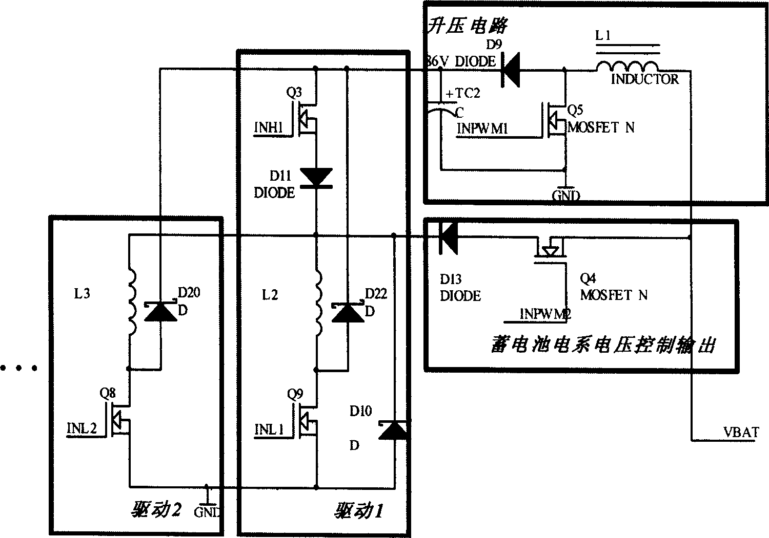
[0019] The principle of the circuit structure is as figure 1 Shown:

[0020] figure 1 The drive 1 in the middle box is a group of drive circuits, in which the field effect transistor Q3 is a high switch; After Q3 is turned off, an energy discharge channel is provided for oil nozzle 1;

[0021] figure 1 The middle box drive 2 is another low-level switch circuit, and multiple sets of low-level switches can be connected under the high-level switch as required.

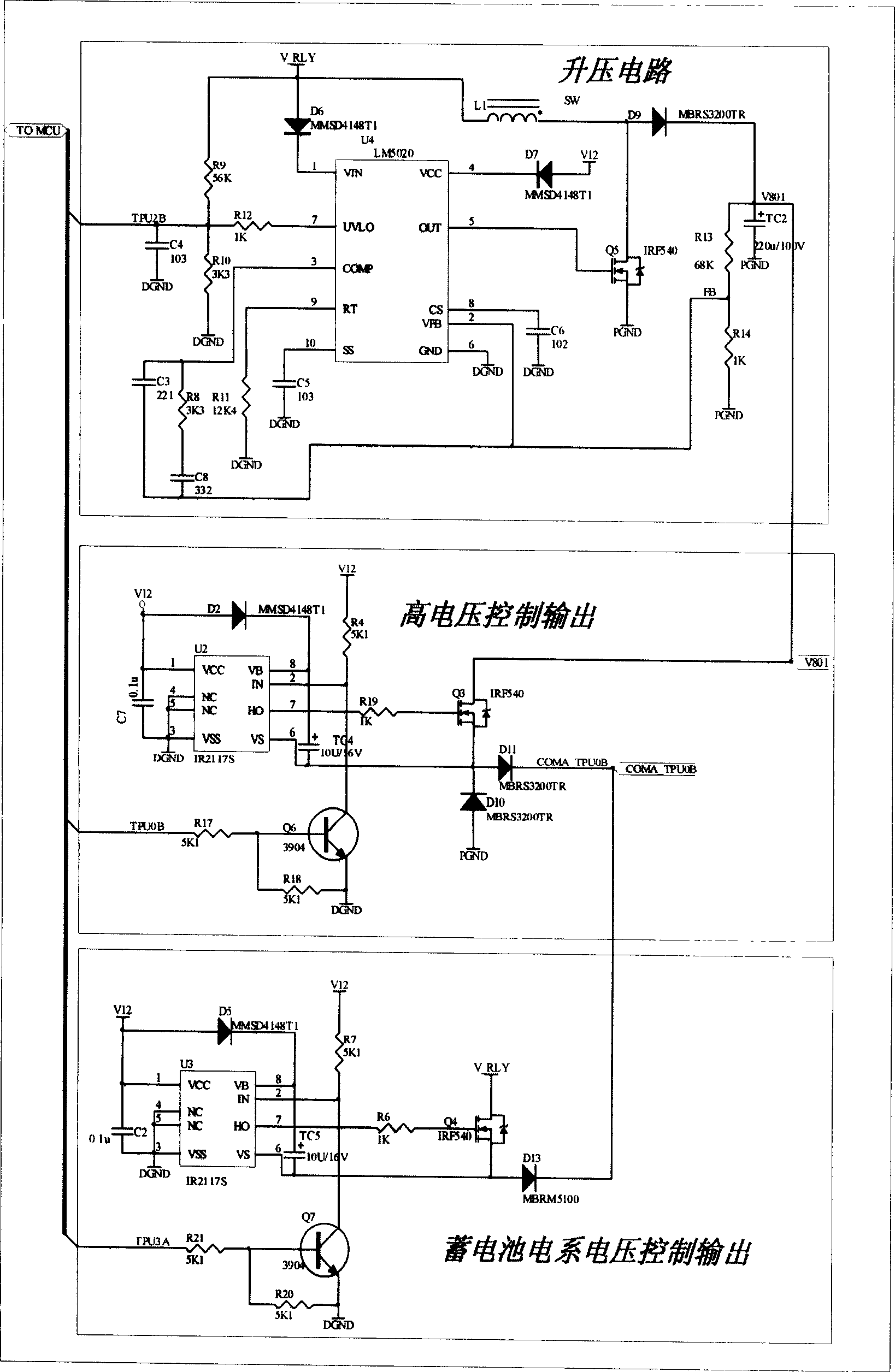
[0022] The specific circuit structure is as follows Figure 3-1 , 3-2 Shown:

[0023] LM5020 is selected as the pulse width modulation controller U4, and IRF540 is selected as the field effect tube;

[0024] In this application circuit, the LM5020 pulse width modulation controller is used to drive the field effect transistor Q5, the inductor L1, the capacitor TC2 and the diode D9 to genera...


PUM


Abstract

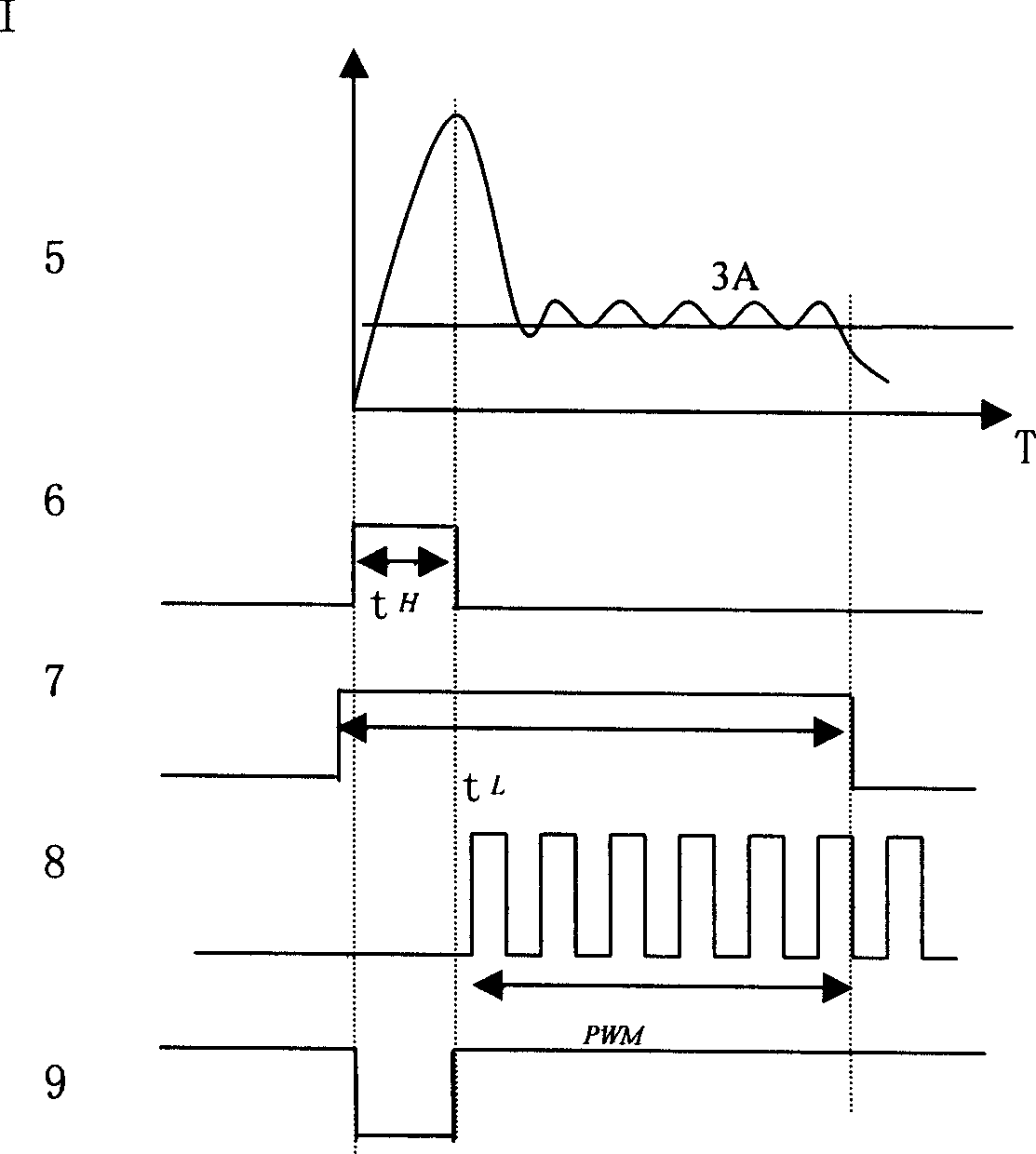
The invention is related to electric control technical area for diesel engine or other area needed for driving electromagnet (valve) in high speed. Drive circuit with power supply in two stages is adopted for controlling fuel injector. Pulse from high voltage power supply supplies instantaneous large current to make electromagnetic valve drive needle valve of fuel injector to be turned to open quickly. Power supply from low voltage maintains needle valve of fuel injector in open state. High voltage is generated from boost up circuit; and amplitude of current for turning needle valve to open quickly is adjusted through pulse width for controlling conduction of high voltage in order to obtain optimal response speed. Low voltage is from accumulator; and amplitude of current is adjusted through PWM mode. Advantages are: favorable quality of fuel jet, and reduced power loss, and raised use ratio of device since switches are multiplexing used for high and low positions.

Description

technical field [0001] The invention is applied to the automobile industry, the technical field of diesel engine electric control or other fields that need to drive high-speed electromagnets (valves), and specifically refers to a high-low switch combination drive circuit with a boost circuit. Background technique [0002] In engine control, in order to achieve good fuel injection quality at high speed, the fuel injector needs to be opened quickly, that is, to provide the fuel injector driving solenoid valve with a high driving voltage with a certain amount of energy that is several times higher than the vehicle battery voltage , so that the electromagnetic coil current rises rapidly to the current required to open the injector needle valve the fastest. Once the needle valve reaches the normal position, only a small current is required to maintain the open state of the needle valve. At the same time, when the solenoid valve coil current is cut off, high reverse self-inductan...

Claims


Application Information

Patent Timeline
Patent Type & Authority Applications(China)
IPC IPC(8): H02J7/00H02M3/07H01F7/18F16K31/06
Inventor 张育华邓金滔
Owner 镇江江奎科技有限公司
Learn More