
Method and apparatus for testing tunnel magnetoresistive effect element, manufacturing method of tunnel magnetoresistive effect element and tunnel magnetoresistive effect element

A technology of tunneling magnetoresistance and manufacturing method, which is applied in the manufacture/processing of electromagnetic devices, functional testing of magnetic heads, and the manufacture of magnetic flux-sensitive magnetic heads, etc., which can solve the problems of costing a lot of manpower and time, and achieve effective and fast mass production The effect of convenient and error-free confirmation

Inactive Publication Date: 2006-02-01
TDK CORPARATION +1
View PDF3 Cites 2 Cited by
  • Summary
  • Abstract
  • Description
  • Claims
  • Application Information

AI Technical Summary

Problems solved by technology

[0006] However, the test method disclosed in U.S. Patent No. 6,473,257 requires a performance test of the TMR read head element such as a TMR read head element electromagnetic conversion performance test, thereby taking a lot of manpower and time for determining the reliability.

Method used


Image

  • Method and apparatus for testing tunnel magnetoresistive effect element, manufacturing method of tunnel magnetoresistive effect element and tunnel magnetoresistive effect element
  • Method and apparatus for testing tunnel magnetoresistive effect element, manufacturing method of tunnel magnetoresistive effect element and tunnel magnetoresistive effect element
  • Method and apparatus for testing tunnel magnetoresistive effect element, manufacturing method of tunnel magnetoresistive effect element and tunnel magnetoresistive effect element

Examples


Embodiment Construction

[0053] Before describing the preferred embodiments of the present invention, the relevant circumstances leading to the present invention will first be introduced.

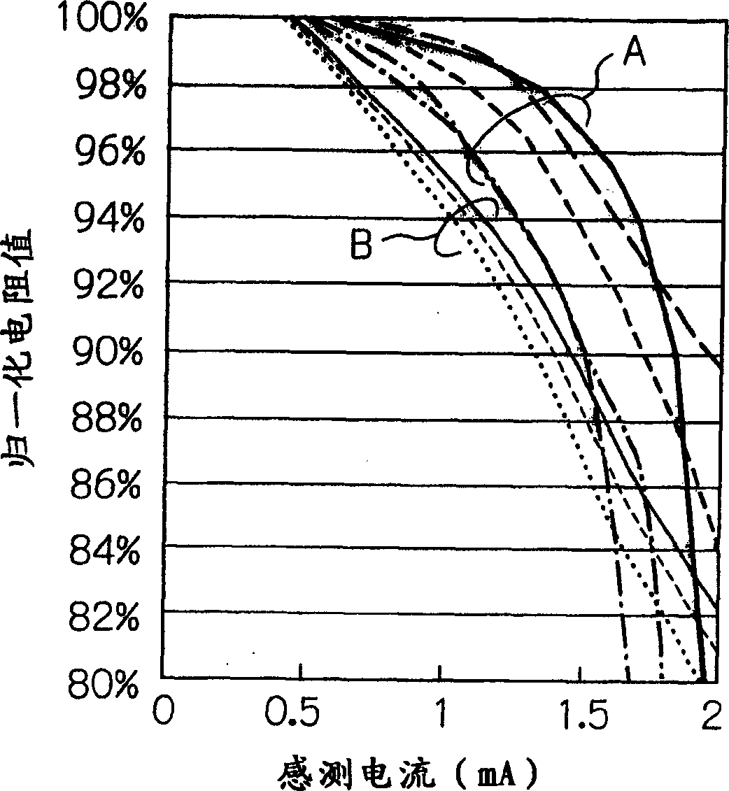
[0054] The inventors of the present application found that when the sensing current flowing through the TMR read head element is increased to a value that may cause breakdown of the element, the TMR read head element dominated by metal conduction and the TMR read head element dominated by tunnel current There are differences in the resistance change characteristics of each TMR read head element among the head elements.

[0055] figure 1 shows the characteristic between the normalized resistance (%) and the sense current Is (mA) for a plurality of TMR read head elements measured by the present inventors.

[0056] As shown in the figure, it should be noted that there are two groups, that is, for group A TMR read head elements, when the sense current increases, its resistance gradually decreases, and for group B TMR ...


PUM


Abstract

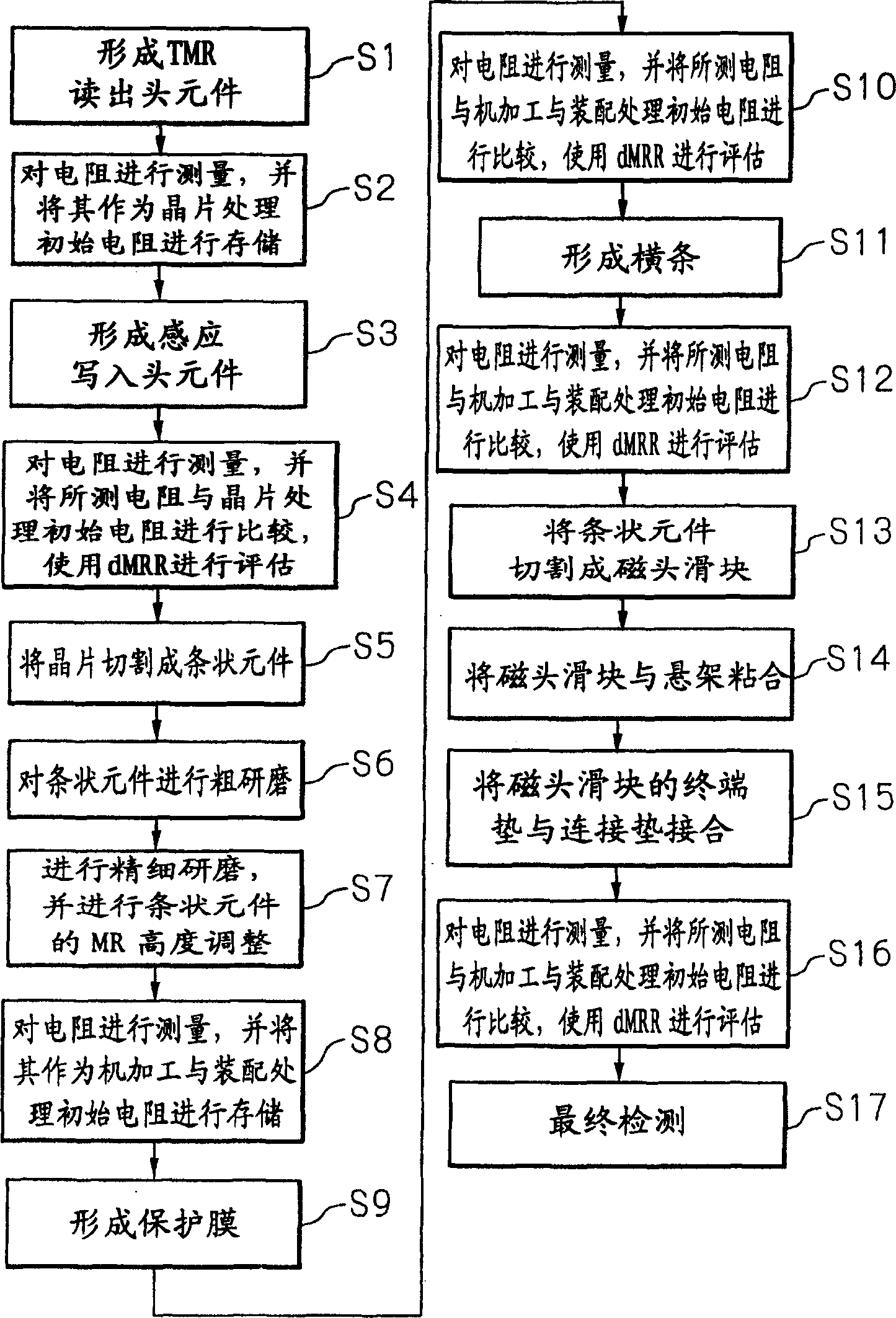
The present invention provides a method for testing a TMR element including a step of measuring a plurality of resistances of the TMR element by feeding a plurality of sense currents with different current values each other through the TMR element, a step of calculating a ratio of change in resistance from the measured plurality of resistances of the TMR element, and a step of evaluating the TMR element using the calculated ratio of change in resistance.

Description

[0001] Cross References to Related Applications [0002] This application claims the benefit of Japanese Patent Application No. 2004-220247 filed on July 28, 2004 and Japanese Patent Application No. 2005-081768 filed on March 22, 2005, which are incorporated herein by reference. technical field [0003] The present invention relates to methods and devices for testing tunnel magnetoresistance (TMR) elements, such as TMR read head elements or magnetoresistance random access memory (MRAM) cells utilizing the tunnel magnetoresistance effect, methods for manufacturing TMR elements, and TMR elements. Background technique [0004] During or after the manufacture of the magnetic head, an evaluation test is generally performed in order to determine whether a thin film magnetic head having a TMR read head element is a defect-free product. This evaluation test includes a reliability test, which is used to confirm whether the breakdown voltage of the MR head element is high enough to w...

Claims


Application Information

Patent Timeline
Patent Type & Authority Applications(China)
IPC IPC(8): G11B5/455G11B5/39H01L43/12H10N50/01
Inventor 蜂须贺望稻毛健治高桥法男清水达司黃柏坚
Owner TDK CORPARATION
Learn More