
An optical communication system for wireless radio signals

An optical communication, radio frequency signal technology, applied in the field of multimode fiber optical communication system, can solve the problem of no description and so on

Inactive Publication Date: 2006-01-18
UNIV COLLEGE OF LONDON +1
View PDF0 Cites 3 Cited by
  • Summary
  • Abstract
  • Description
  • Claims
  • Application Information

AI Technical Summary

Problems solved by technology

The disadvantages of these methods are: first, special installation of fiber is required (because most fiber optic base stations installed in buildings are multimode); second, in order to stabilize and lock the Remote local oscillator, need to transmit low frequency reference frequency (tone) at the same time
This interruption problem can be easily found from accurate measurement of EVM, but it has not been described in the prior art

Method used


Image

  • An optical communication system for wireless radio signals
  • An optical communication system for wireless radio signals
  • An optical communication system for wireless radio signals

Examples


Embodiment Construction

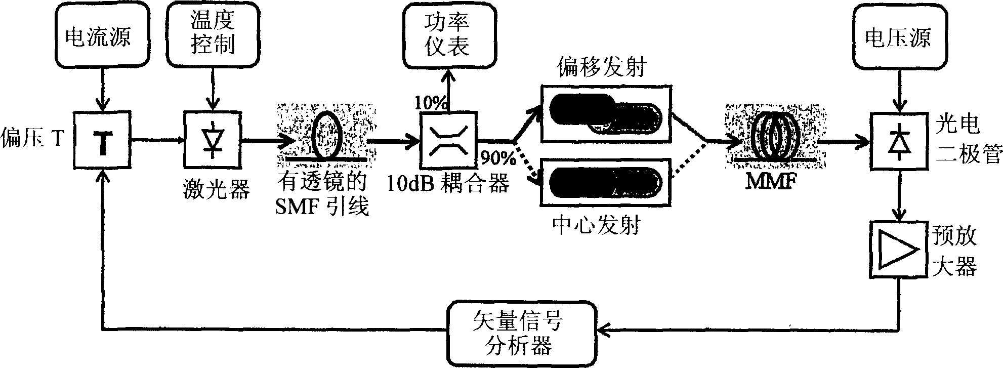
[0028] Refer to the attached drawings and first to the figure 1 , the optical communication system 11 according to the preferred embodiment of the present invention comprises a signal input device 12; Optical radiation source 13; Temperature monitoring device 14; Lensed single-mode fiber (SMF) 15; Optical fiber to fiber optic coupler 16; Power monitoring device 17 ; Transmitting device 18; Multimode fiber 19; Photodetector 20; Signal amplifying device 21; Signal analyzing device 22;

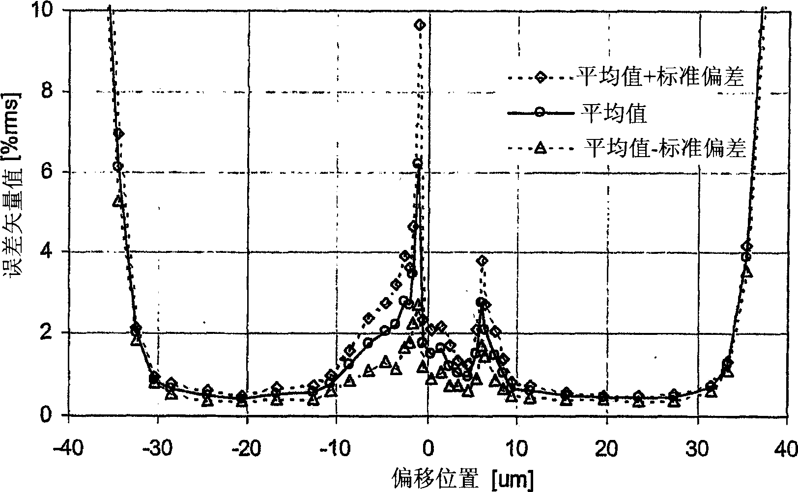
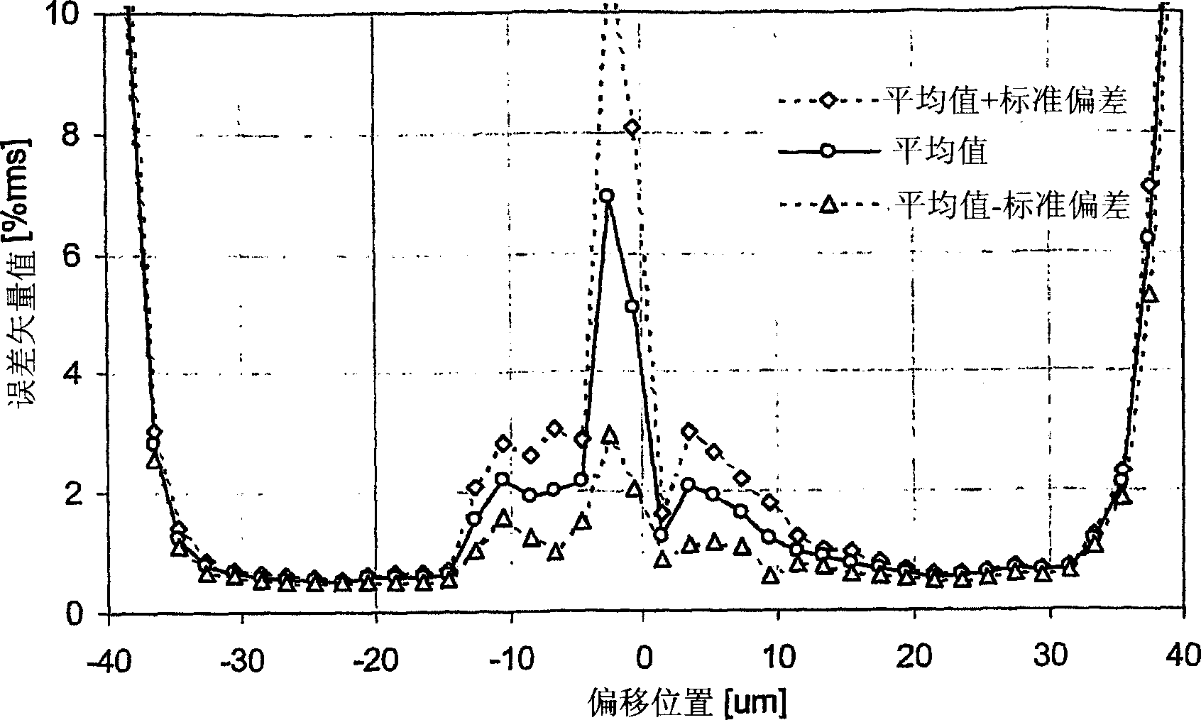
[0029] In order to judge the best strategy for high-quality transmission of fiber-optic RF signals in multimode fiber, in a series of experiments, a complex digital modulation format (32-QAM) was used in "worst-case" multimode fiber at high frequency RF The transmission of the signal defines the emission and measures the result. In each case, the offset launch has better performance than the center launch due to less variability over time, which means that in a multimode fiber network, the offse...


PUM


Abstract

A method of transmission of radio signals over all types of graded-index multimode fibre is provided. The method comprises launching optical radiation into the core of the multimode fibre away from the centre of the core so as to strongly excite a subset of the available modes of the multimode fibre. The subset of modes excited are within a small number of mode groups and thus have similar propagation constants leading to a reduction in modal dispersion and modal interference and smoothing of the frequency response passband region beyond the fibres specified 3dB base band bandwidth assisting RF transmission and recovery from this region

Description

technical field [0001] The present invention relates to an optical communication system, and more particularly to an optical communication system comprising a multimode optical fiber installed in or connected to partitioned spaces such as corporate office buildings, shopping malls, subways and airports. Background technique [0002] In-building coverage is an important and growing market for network operators and building owners who wish to deploy cellular radio or wireless LAN systems in buildings. The most effective and efficient way to provide this cabling is to place base stations throughout the building and use an Antenna Distribution System (DAS) to provide relatively uniform signal strength. DAS can be built using coaxial cable, but for longer spans, fiber optics are better because their insertion loss is essentially independent of link length, simplifying system design and future expansion. [0003] Today, analog optical links using radio over fiber (radio over fibe...

Claims


Application Information

Patent Timeline
Patent Type & Authority Applications(China)
IPC IPC(8): H04B10/13H04B7/26H04B10/2575H04B10/2581
CPCH04B10/25752H04B10/2575H04B10/2581
Inventor 约翰·阿尔文·西兹戴维·韦克维森特·理查德·彭蒂马修·韦伯斯特彼得·哈特曼休·伊恩·怀特
Owner UNIV COLLEGE OF LONDON
Learn More