Eureka AIR delivers breakthrough ideas for toughest innovation challenges, trusted by R&D personnel around the world.

Image forming apparatus and process cartridge

An imaging device and device technology, applied in the fields of electrical recording process equipment, electrical recording technology, optics, etc. that apply charge patterns, can solve the problems of undeveloped photoreceptor, blurred image and black spots, and easy generation of image memory, etc. Achieve the effect of suppressing blur and black spots, suppressing image memory, suppressing blur and black spots and image memory

Active Publication Date: 2006-01-18
FUJIFILM BUSINESS INNOVATION CORP +1
View PDF4 Cites 8 Cited by
  • Summary
  • Abstract
  • Description
  • Claims
  • Application Information

AI Technical Summary

Problems solved by technology

[0006] However, in the above technique, if the time required from charging to the developing process changes, the quality of the image will be insufficient.
When the imaging mode is switched to another imaging mode, the time required for the process from charging to developing changes, but a photoreceptor that can fully adapt to the change under usage conditions has not been developed yet
Therefore, there is a problem in these technologies that when the process from charging to developing takes a long time and imaging is performed under this processing condition, serious image blur and black spots tend to occur, and image memory tends to occur

Method used


Image

  • Image forming apparatus and process cartridge
  • Image forming apparatus and process cartridge
  • Image forming apparatus and process cartridge

Examples


preparation example Construction

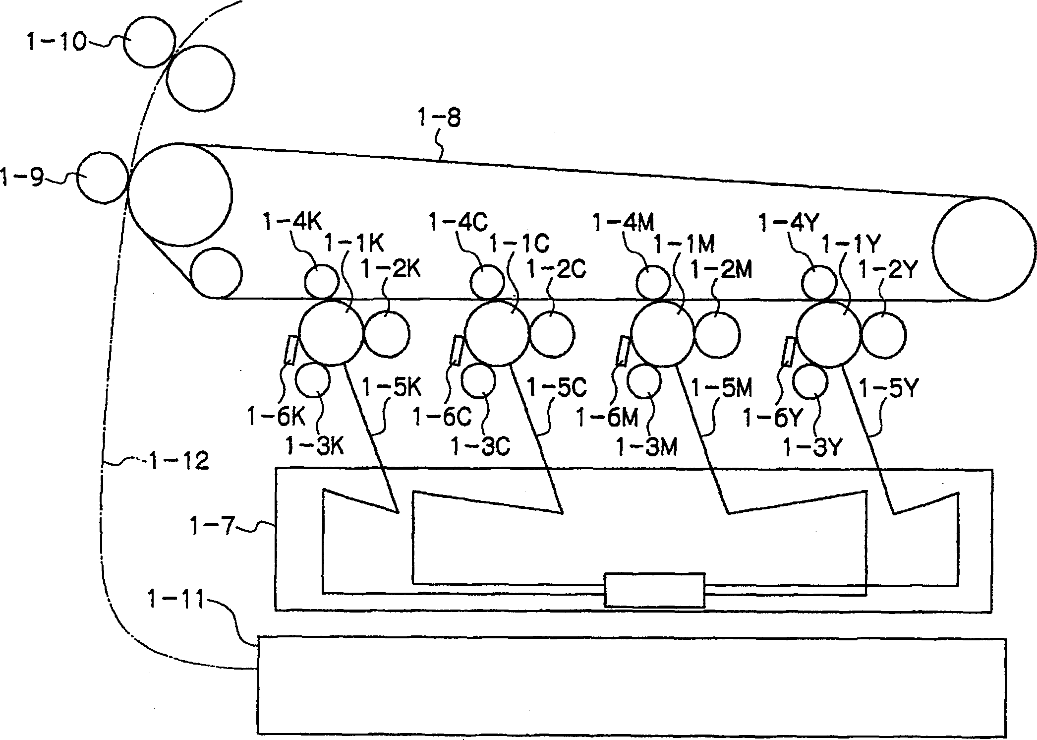
[0274] The preparation method of the spherical toner is not particularly limited, and a known method can be used for preparation. For example, any one of the following methods is used: kneading and pulverizing; a method including obtaining particles by kneading and pulverizing, and then adjusting the shape of the particles by mechanical impact, force or thermal energy; emulsion polymerization; and a dissolution-suspension method. In one embodiment, the spherical toner obtainable using any of the methods described above is a core to which aggregated particles are adhered, followed by heating and melting, thereby producing a toner having a core-shell structure. In one embodiment, when the external additive is added, the toner is prepared by mixing the spherical toner and the external additive with a Henschel mixer or a V-type mixer. When a spherical toner is produced by a wet method, external additives may be added by a wet method.

[0275] The intermediate transfer member 1-8 ...

Embodiment 1

[0287] Under stirring, 100 parts by weight of zinc oxide (average particle diameter 70nm, specific surface area 15m 2 / g, produced by Tayka Corporation) was mixed with 500 parts by weight of tetrahydrofuran. 1.25 parts by weight of a silane coupling agent (KBM603 produced by Shin-etsu Chemical Co., Ltd.) was added thereto, and the mixture was stirred for 2 hours. Then tetrahydrofuran was distilled off under reduced pressure to obtain zinc oxide particles coated with a silane coupling agent, which were calcined at 120° C. for 3 hours to obtain a surface-treated zinc oxide pigment.

[0288] 15 parts by weight of butyral resin (BM-1 produced by Sekisui Chemical Co., Ltd.) was dissolved in 85 parts by weight of methyl ethyl ketone to obtain a solution, and 38 parts by weight of the resulting solution was mixed with 60 parts by weight of the zinc oxide pigment obtained above, 25 parts by weight Parts of methyl ethyl ketone, 0.6 parts by weight of alizarin and 13.5 parts by weight ...

Embodiment 2~4

[0293] An electrophotographic photoreceptor was produced in the same manner as in Example 1 except that the metal oxide and acceptor compound for surface treatment were changed to those shown in Table 1. The properties of the obtained photoreceptor were evaluated in the same manner as in Example 1. The results are listed in Table 1.


PUM


Abstract

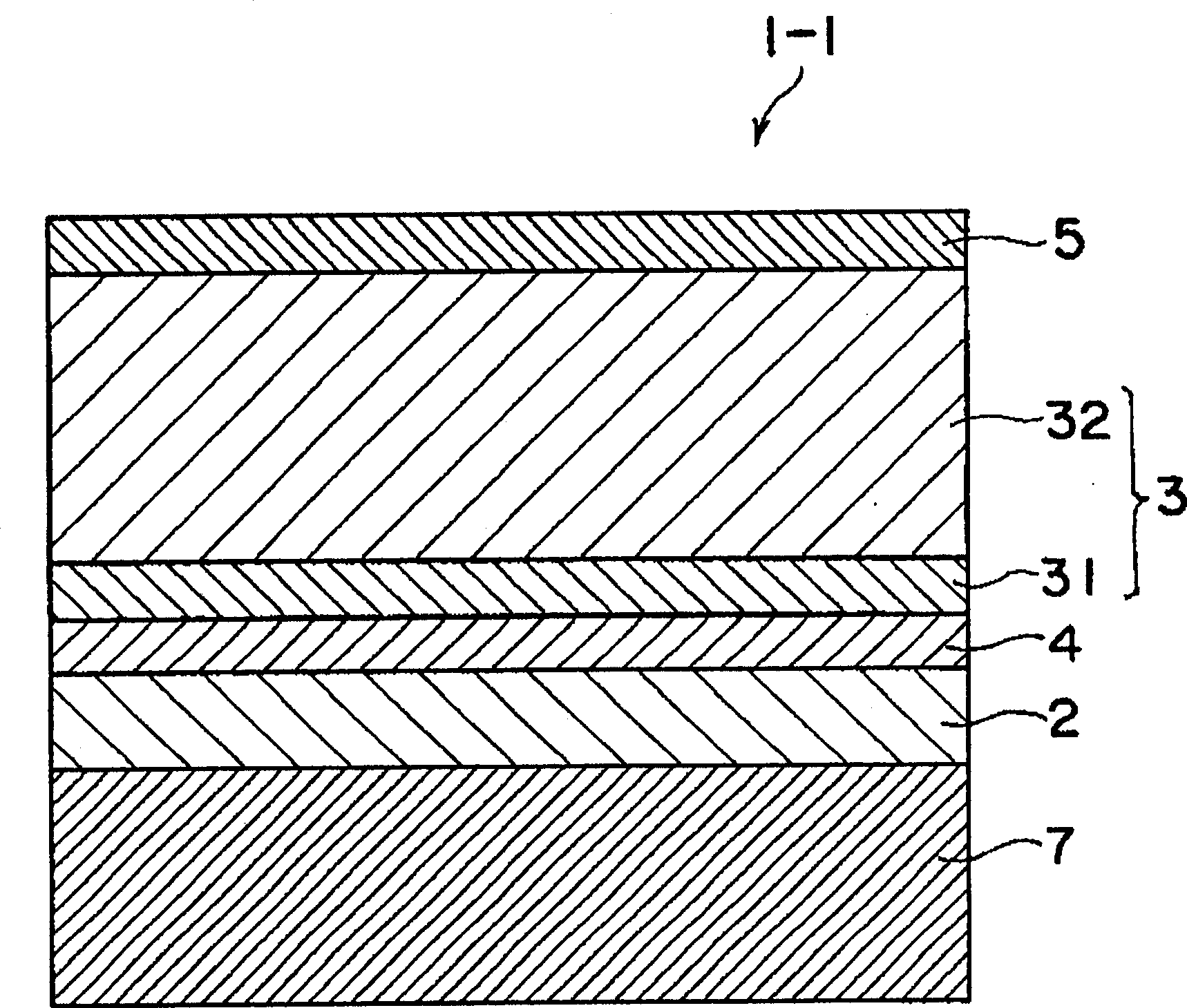
The present invention provides an image forming apparatus. An image forming apparatus comprising an electrophotographic photoreceptor, a charging unit, an exposure unit, a development unit, and a transfer unit, wherein the image forming apparatus conducts charging, exposure, development, and transfer while moving a circumferential surface of the electrophotographic photoreceptor in a predetermined direction, the image forming apparatus further comprises a controlling unit which controls a moving velocity of the circumferential surface of the electrophotographic photoreceptor so that a time required for processes from charging to development is changeable, the electrophotographic photoreceptor includes an undercoat layer and a photosensitive layer, and the undercoat layer includes a metal oxide particle and an acceptor compound having a group capable of reacting with the metal oxide particle.

Description

technical field [0001] The present invention relates to an image forming apparatus and a process cartridge. Background technique [0002] Since the electrophotographic technology is capable of high-speed and high-quality printing, it is possible to apply the electrophotographic technology to electrophotographic apparatuses such as copiers and laser printers. [0003] In recent years, organic photoreceptors containing photoconductive organic materials have become the mainstream of photoreceptors used in electrophotographic devices. Regarding the composition of the photoreceptor, a functionally separated photoreceptor in which a charge generating material and a charge transporting material are dispersed in separate layers (charge generating layer and charge transporting layer) has been used. [0004] In recent years, with the improvement in quality and speed of office affairs processing, high-speed and colored document processing is required, and high-speed, colored and high-...

Claims


Application Information

Patent Timeline
Patent Type & Authority Applications(China)
IPC IPC(8): G03G5/147G03G5/00G03G15/00G03G21/16
CPCG03G2215/0119G03G2215/00957G03G15/5008
Inventor 额田秀美中村博史星崎武敏齐愉胡南星何银墉
Owner FUJIFILM BUSINESS INNOVATION CORP
Why Eureka
Eureka Blog
Learn More