Light intensity modulation element, intensity-modulated-light generating device, laser exposure unit and photograph processing apparatus
A technology for modulating components and light intensity, which can be used in developing and printing devices, light control, instruments, etc. It can solve the problems of large size, difficulty in miniaturization of light intensity modulation components, long optical length, etc., and achieves adjustable light intensity and compact structure , to achieve the effect of conversion efficiency
- Summary
- Abstract
- Description
- Claims
- Application Information
AI Technical Summary
Problems solved by technology
Method used
Image
Examples
Embodiment approach 1
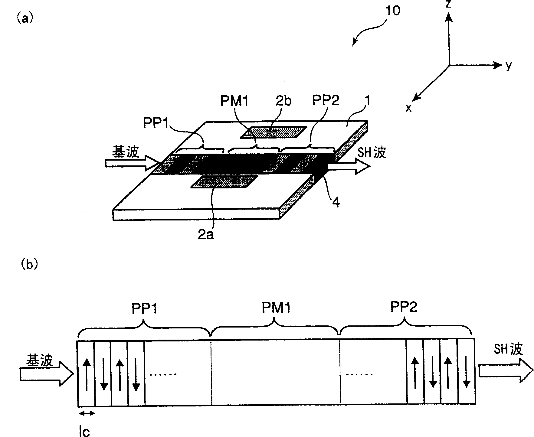
[0074] image 3 (a) is a schematic diagram explaining one embodiment of the light intensity modulation element related to the present invention. in addition, image 3 (b) is a longitudinal sectional view illustrating a polarization structure in an embodiment of the light intensity modulation element related to the present invention, and is taken at image 3 (a) is a cross-sectional view of the center of the optical waveguide along the direction of the optical waveguide.
[0075] An optical waveguide 4 for guiding laser light is linearly formed in the central portion of the rectangular substrate 1 in the width direction. After that, the phase modulation electrodes 2 a and 2 b are provided so as to sandwich the optical waveguide 4 .
[0076] Substrate 1 is made of nonlinear optical crystal LiNbO 3 (LN: lithium niobate). The LiNbO 3 It is a ferroelectric crystal that exhibits a secondary nonlinear optical effect, and has the property of changing the refractive index when an...
Embodiment approach 2
[0108] In Embodiment 1 above, the light intensity modulation element 10 has two periodic polarization inversion parts and one non-polarization part, and the phase modulation is performed by the applied voltage in the non-polarization part, that is, the SH wave is performed. intensity modulation. In this embodiment, in addition to the structure of Embodiment 1, an optical intensity modulation element having a structure of one periodic polarization inversion portion and one non-polarization portion will be described. In addition, the newly added periodic polarization inversion part and non-polarization part are referred to as calibration parts according to needs.
[0109] Figure 5 It is a schematic diagram illustrating one embodiment of the light intensity modulation element related to the present invention. Portions assigned the same reference numerals as those in Embodiment 1 have the same functions and structures, and therefore description thereof will be omitted. In addi...
Embodiment approach 3
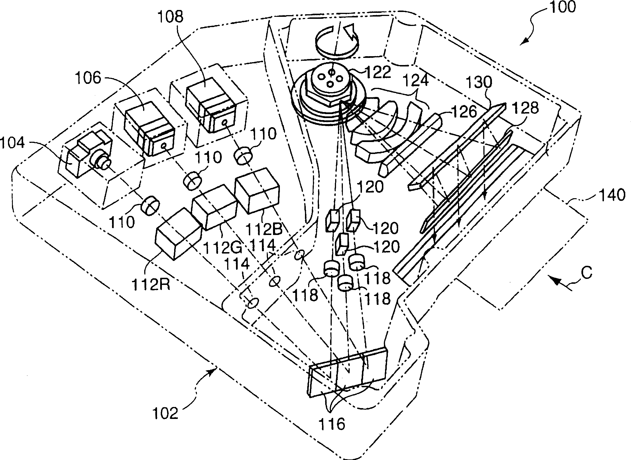
[0128] The optical intensity modulation elements 10 and 20 in Embodiments 1 and 2 above have a periodic polarization inversion portion and a non-polarization portion, and phase modulation can be performed by a voltage applied to the non-polarization portion, that is, SH Wave intensity modulation. In this embodiment, a laser light source including the light intensity modulation elements 10 and 20 , that is, an intensity modulation light generator will be described. The intensity modulated light generator, with figure 2 The combined functions of the laser light source 106 (or 108 ), the collimator lens 110 and the light intensity modulation element 112G (or 112B) in the shown laser exposure device.
[0129] Figure 7 It is a perspective view illustrating an embodiment of the intensity-modulated light generator L related to the present invention. The laser device L includes a laser generator 30 including a semiconductor laser 36 , and a light intensity modulation element 20 t...
PUM
 Abstract
Description
Claims
Application Information
 - R&D
- Intellectual Property
- Life Sciences
- Materials
- Tech Scout
- Unparalleled Data Quality
- Higher Quality Content
- 60% Fewer Hallucinations
Browse by: Latest US Patents, China's latest patents, Technical Efficacy Thesaurus, Application Domain, Technology Topic, Popular Technical Reports.
© 2025 PatSnap. All rights reserved.Legal|Privacy policy|Modern Slavery Act Transparency Statement|Sitemap|About US| Contact US: help@patsnap.com


