Raman amplifier
A Raman amplifier, light wave technology, used in instruments, lasers, phonon exciters, etc., can solve problems such as gain change
- Summary
- Abstract
- Description
- Claims
- Application Information
AI Technical Summary
Problems solved by technology
Method used
Image

Examples
no. 1 example
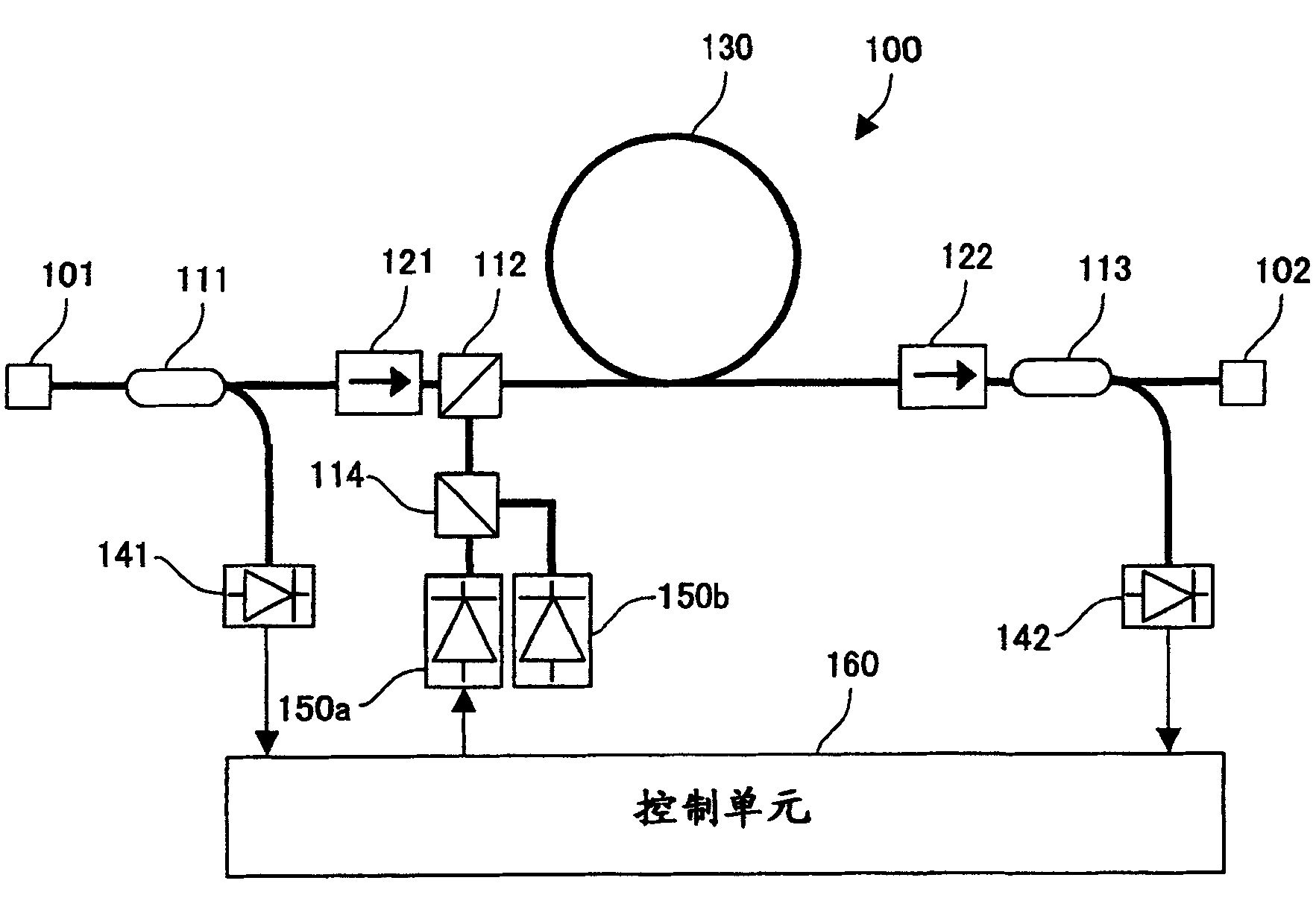
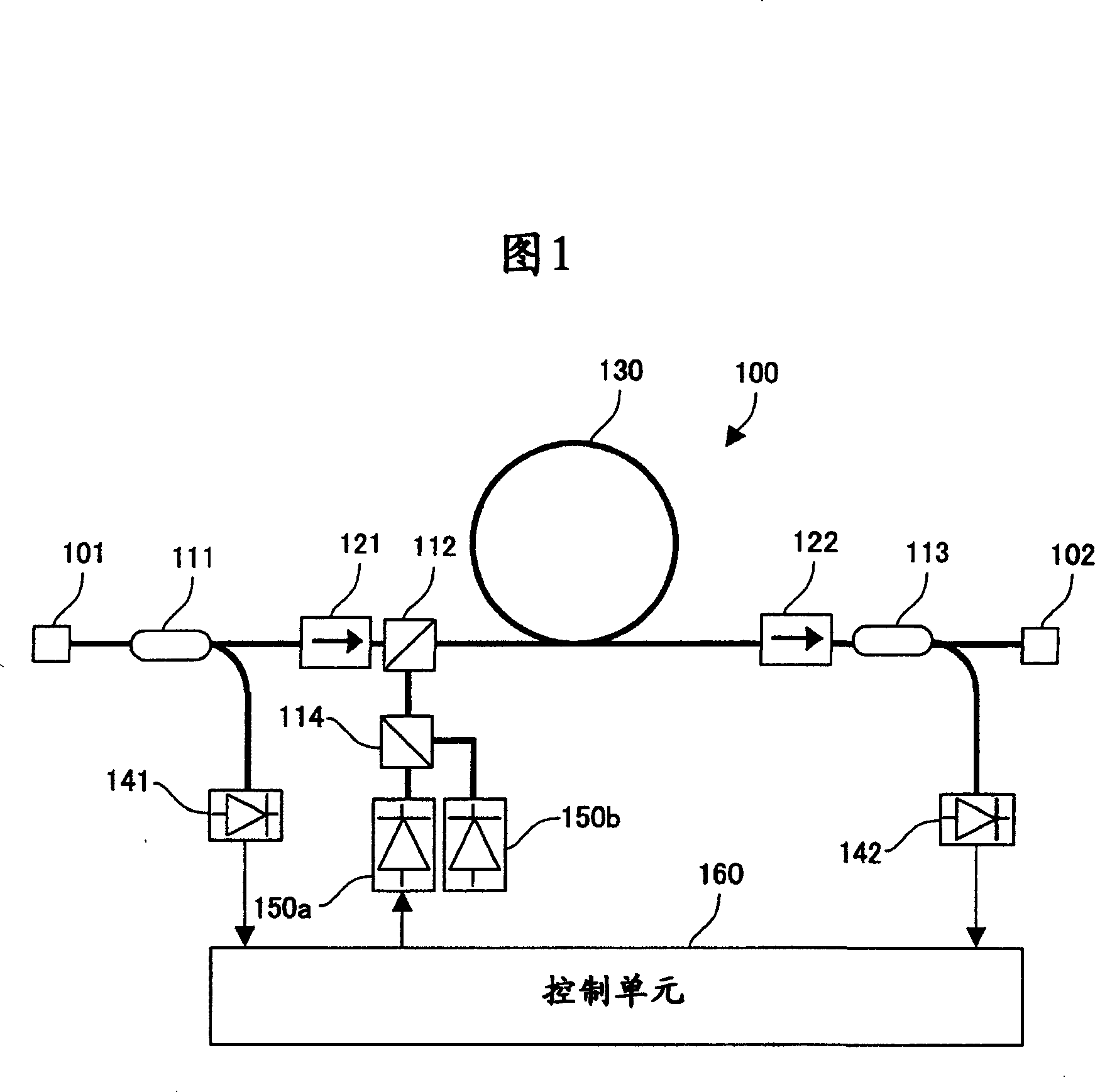
[0037] FIG. 1 is a conceptual diagram illustrating a Raman amplifier 100 of a first embodiment of the present invention. In the Raman amplifier 100, a signal light wave (input light wave) enters at the optical input terminal 101 to be amplified by Raman. The Raman-amplified signal light wave (output light wave) is emitted from the light output port 102 . This Raman amplifier 100 is provided with fiber coupler 111, optical isolator 121, fiber coupler 112, Raman amplifying fiber 130, An optical isolator 122 and a fiber coupler 113 . In addition, this Raman amplifier 100 is also provided with a photodiode 141 connected to the fiber coupler 111, a fiber coupler 114 connected to the fiber coupler 112, laser diodes 150a and 150b connected to the fiber coupler 114, connected to the fiber coupler The photodiode 142 of the detector 113 and the control unit 160 connected to the photodiodes 141 and 142 and the laser diode 150a.
[0038] The optical fiber coupler 111 branches the signa...
no. 2 example
[0053] In the first embodiment, pump light waves having a plurality of wavelengths are supplied to the optical fiber in the same direction as signal light waves. In the second embodiment described below, pump light waves having a plurality of wavelengths are supplied to the optical fiber in a direction opposite to that of the signal light waves. FIG. 4 is a conceptual diagram illustrating a Raman amplifier 200 of a second embodiment of the present invention. In the second embodiment, a fiber coupler 115 for supplying pumping light waves having a plurality of wavelengths to the optical fiber 130 is provided between the optical fiber 130 and the optical isolator 122 on the path of the signal light wave.
[0054] The fiber coupler 115 receives pump light waves having a plurality of wavelengths output from the fiber coupler 114 and supplies them to the Raman amplifying fiber 130 . In addition, the fiber coupler 115 receives the signal light wave output from the optical fiber 130 ...
no. 3 example
[0059] When the inventors studied the first and second embodiments and other cases, they found that there is a relationship between the power of the pump light wave having the shortest wavelength that makes the gain of Raman amplification constant and the power of the input signal light wave.
[0060] 7 is a graph showing the power of the input signal light wave and the pump light wave with the shortest wavelength (from the laser diode 150a output, its wavelength is 1,435.4nm) power relationship. The power of the input signal light wave and the power of the pump light wave having the shortest wavelength have a relationship expressed as a linear function.
[0061] The third embodiment utilizes this relationship to control the gain of Raman amplification. FIG. 8 is a conceptual diagram illustrating a Raman amplifier 300 of a third embodiment of the present invention. The control unit 160 illustrated in FIG. 8 receives only the electrical signal output from the photodiode 141 ....
PUM
 Abstract
Description
Claims
Application Information
 - Generate Ideas
- Intellectual Property
- Life Sciences
- Materials
- Tech Scout
- Unparalleled Data Quality
- Higher Quality Content
- 60% Fewer Hallucinations
Browse by: Latest US Patents, China's latest patents, Technical Efficacy Thesaurus, Application Domain, Technology Topic, Popular Technical Reports.
© 2025 PatSnap. All rights reserved.Legal|Privacy policy|Modern Slavery Act Transparency Statement|Sitemap|About US| Contact US: help@patsnap.com