Method and device for temperature compensation of radio frequency equipment

A technology of temperature compensation device and radio frequency equipment, applied in transmitter monitoring, receiver monitoring and other directions, can solve problems such as the influence of radio frequency equipment gain, and achieve the effect of small gain change

Active Publication Date: 2018-03-09
SHENZHEN CITY SIGLENT TECH
View PDF7 Cites 0 Cited by
  • Summary
  • Abstract
  • Description
  • Claims
  • Application Information

AI Technical Summary

Problems solved by technology

[0004] This application provides a method and device for temperature compensation of radio frequency equipment, which can solve the problem that the gain of radio frequency equipment will be affected by changes in ambient temperature, and reduce the gain error

Method used


Image

  • Method and device for temperature compensation of radio frequency equipment
  • Method and device for temperature compensation of radio frequency equipment
  • Method and device for temperature compensation of radio frequency equipment

Examples


Embodiment 1

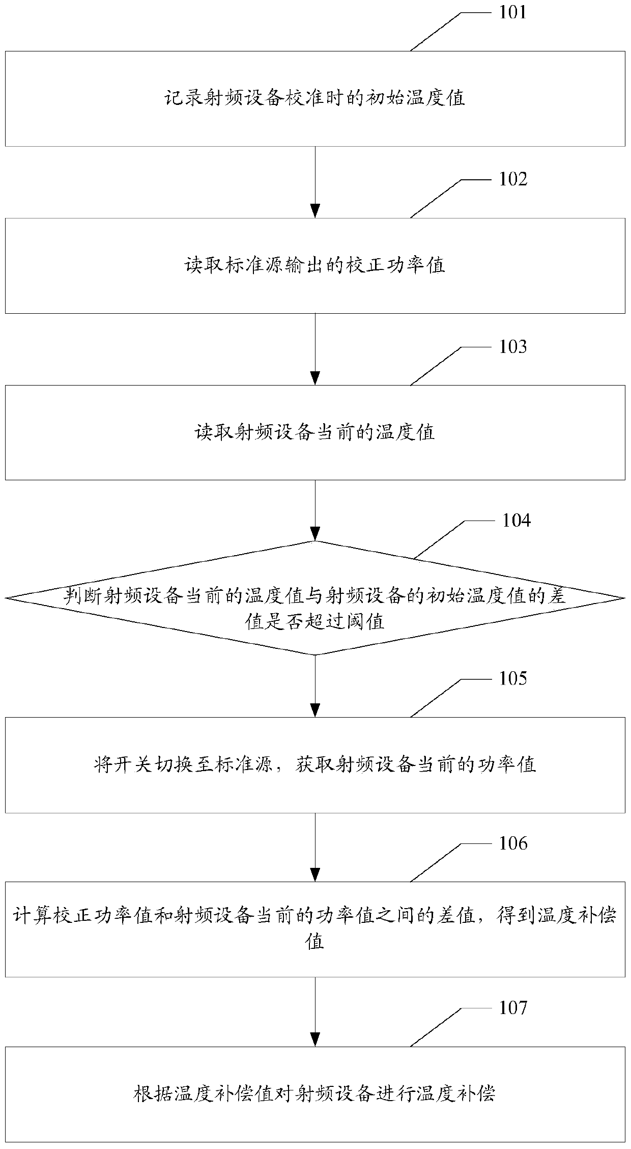
[0026] Please refer to figure 1 , figure 1 It is a flow chart of the method in Embodiment 1 of the present invention. Such as figure 1 As shown, a method for temperature compensation of a radio frequency device may include the following steps:

[0027] 101. Record the initial temperature value when the radio frequency device is calibrated.

[0028] The initial temperature value is the temperature value of the radio frequency device when it is working normally. When working at this temperature value, the gain of the radio frequency equipment will not be affected.

[0029] 102. Read the corrected power value output by the standard source.

[0030] The corrected power value represents the power of the radio frequency device when it works at the initial temperature value.

[0031] The standard source can keep the output power constant without being affected by the external ambient temperature. The corrected power of the standard source can be used to compare with the power ...

Embodiment 2

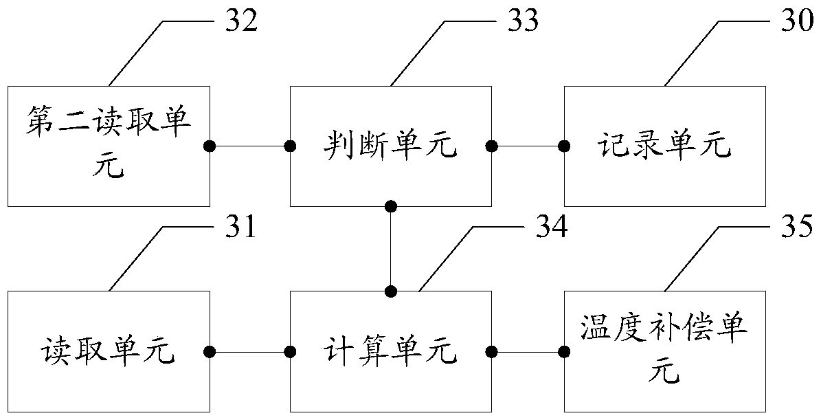
[0064] Correspondingly, this application also provides a temperature compensation device for radio frequency equipment, please refer to image 3 , image 3 It is a schematic diagram of the device structure implemented by the present invention. Such as image 3 As shown, the radio frequency equipment temperature compensation device may include:

[0065] The recording unit 30 is configured to record the initial temperature value when the radio frequency device is calibrated.

[0066] The reading unit 31 is configured to read the corrected power value output by the standard source, the corrected power value represents the power of the radio frequency device when it works at the initial temperature value.

[0067] The second reading unit 32 is configured to read the current temperature value of the radio frequency device.

[0068] A judging unit 33, configured to judge whether the difference between the current temperature value of the radio frequency device and the initial te...


PUM


Abstract

The radio frequency equipment temperature compensation method and device provided by this application record the initial temperature value when the radio frequency equipment is calibrated, read the corrected power value output by the standard source and the current temperature value of the radio frequency equipment, and judge the current temperature value of the radio frequency equipment and the temperature of the radio frequency equipment. Whether the difference of the initial temperature value exceeds the threshold value, if so, switch the switch to the standard source, obtain the current power value of the radio frequency device, then switch to the main channel of the radio frequency device, and calculate the corrected power value and the current power value of the radio frequency device The temperature compensation value is obtained, and then the temperature compensation of the radio frequency equipment is performed according to the temperature compensation value. A standard source is a stable source that maintains an output amplitude variation between ‑0.1dB to +0.1dB with little change in gain. During the operation of the radio frequency equipment, it can be compared with the standard source in real time, and the influence of temperature on the channel gain can be compensated in real time, thus ensuring that the radio frequency equipment is accurately calibrated and less affected by temperature.

Description

technical field [0001] The present application relates to a method and device for temperature compensation of radio frequency equipment. Background technique [0002] The gain of the existing radio frequency equipment is placed with the temperature compensation device. The gain of the radio frequency equipment will change with the change of the ambient temperature, which will cause the reading of the calibrated machine to become inaccurate, resulting in the measurement results being affected. big impact. Therefore, in order to ensure the accuracy of the gain of the radio frequency device, it is necessary to compensate the characteristics of channel temperature changes. [0003] In the prior art, there are two methods for temperature compensation of radio frequency equipment: The first method is to place a temperature compensation device on the radio frequency equipment, or to collect the high and low temperature characteristics of some prototypes, and then make a temperatur...

Claims


Application Information

Patent Timeline
Patent Type & Authority Patents(China)
IPC IPC(8): H04B17/13H04B17/21
Inventor 郑翠翠
Owner SHENZHEN CITY SIGLENT TECH
Why Eureka
Try Eureka