
Antenna device

An antenna device, loop antenna technology, applied in the direction of antenna, antenna support/mounting device, loop antenna, etc., can solve the problem of changing the size of the authentication area

Inactive Publication Date: 2012-11-28
PANASONIC CORP
View PDF9 Cites 0 Cited by
  • Summary
  • Abstract
  • Description
  • Claims
  • Application Information

AI Technical Summary

Problems solved by technology

[0003] However, the antenna gain changes according to the distance between the authentication key and the human body, and there is a problem that the size of the authentication area changes

Method used


Image

  • Antenna device
  • Antenna device
  • Antenna device

Examples


Embodiment approach 1

[0093] Next, details of Embodiment 1 of the antenna device of the present invention will be described.

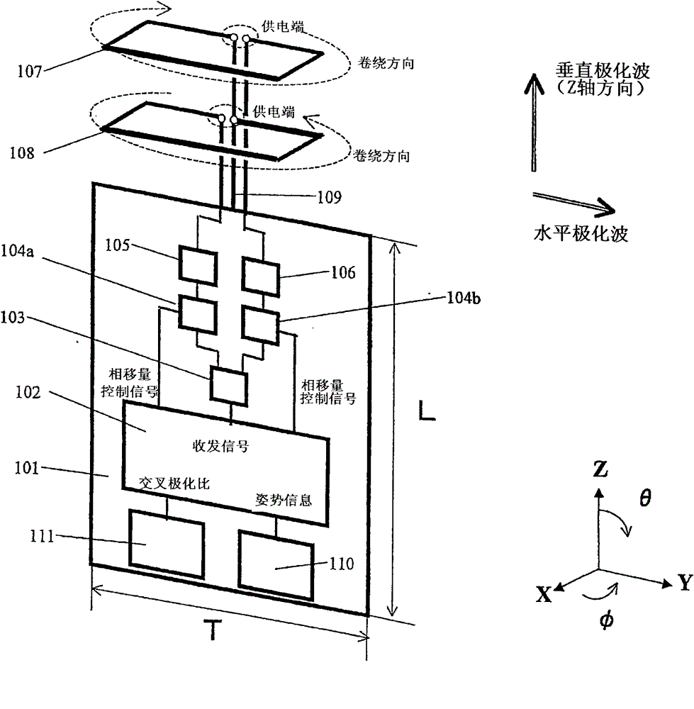
[0094] figure 1 It is a figure which shows the structure of the antenna apparatus of this invention. X, Y, and Z represent respective coordinate axes. exist figure 1 Among them, the ground plate 101 is a ground plate having a ground conductor. The length direction of the ground plate 101 is the Z-axis direction. That is, the length L in the Z-axis direction of the ground plate 101 is greater than the length T in the X-axis direction. However, the length L of the ground plate 101 may be approximately the same as the length T.

[0095] The transceiver circuit 102 is provided on the ground plane 101 and is a transceiver circuit that generates and outputs a transmission signal and processes an input reception signal. Wherein, the transceiver circuit 102 may also be only a transmitting circuit or a receiving circuit. In addition, the inclination information of the antenna d...


PUM


Abstract

To provide an antenna device which can reduce change of a gain by a human body. The antenna device includes a magnetic flow antenna (401) using a magnetic flow as a radiation source; a current antenna (402) using current as a radiation source; and a current magnetic flow distribution control circuit (403) which supplies signals to the magnetic flow antenna (401) and the current antenna (402). Themagnetic flow antenna (401) and the current antenna (402) are arranged so that a polarized wave emitted from the magnetic flow antenna (401) and a polarized wave emitted from the current antenna (402) intersect orthogonally. The current magnetic flow distribution control circuit (403) controls distribution of radio waves emitted from the magnetic flow antenna (401) and the current antenna (402).

Description

technical field [0001] The present invention relates to an antenna device using a loop antenna element. Background technique [0002] In recent years, in order to ensure information security, wireless personal authentication technology represented by SPC (Secure Private Cosm) has been actively developed. The distance detection based on mutual authentication and RSSI (Received Signal Strength Indicator) is always performed between the authentication key with wireless communication function held by the user and the controlled device with wireless communication function such as personal computer, mobile phone, and car. Use the strength of RSSI to judge whether the controlled device is in the authentication area (within a few meters around the authentication key), and control the action of the function lock and alarm buzzer of the controlled device. Thereby, the function of preventing others from illegally using or forgetting to leave the place is realized. When the authentica...

Claims


Application Information

Patent Timeline
Patent Type & Authority Patents(China)
IPC IPC(8): H01Q1/24H01Q3/26H01Q7/00H01Q21/28H04B1/38H04B1/44
Inventor 宫下功宽
Owner PANASONIC CORP
Learn More