
Control method for an exhaust gas purification system and an exhaust gas purification system

A technology of exhaust gas purification system and control method, applied in electrical control, charging system, engine control and other directions, can solve problems such as engine damage and EGR passage blockage, and achieve the effect of preventing damage and preventing fixation

Inactive Publication Date: 2005-11-02
ISUZU MOTORS LTD
View PDF3 Cites 3 Cited by
  • Summary
  • Abstract
  • Description
  • Claims
  • Application Information

AI Technical Summary

Problems solved by technology

[0012] However, when exhaust gas containing a large amount of unburned fuel under forced regeneration control by post-injection or direct injection in the exhaust pipe flows into the exhaust pipe, the EGR system (exhaust gas recirculation system) is activated, and EGR, which is part of the exhaust gas, is sent to the intake air. When side inflow occurs, a large amount of unburned fuel flows into the EGR passage and the intake side passage of the engine. Therefore, blockage of the EGR passage or sticking of the intake valve exposed from the intake (inlet) port of the cylinder head of the engine may occur. In addition, there is a problem of engine damage due to these obstacles

Method used


Image

  • Control method for an exhaust gas purification system and an exhaust gas purification system
  • Control method for an exhaust gas purification system and an exhaust gas purification system
  • Control method for an exhaust gas purification system and an exhaust gas purification system

Examples


Embodiment Construction

[0025] Hereinafter, with reference to the accompanying drawings, taking an exhaust gas purification system of a continuous regenerative DPF device combined with an oxidation catalyst and a filter with a catalyst as an example, the control method and the exhaust gas purification system of the embodiment of the present invention will be described. purification system.

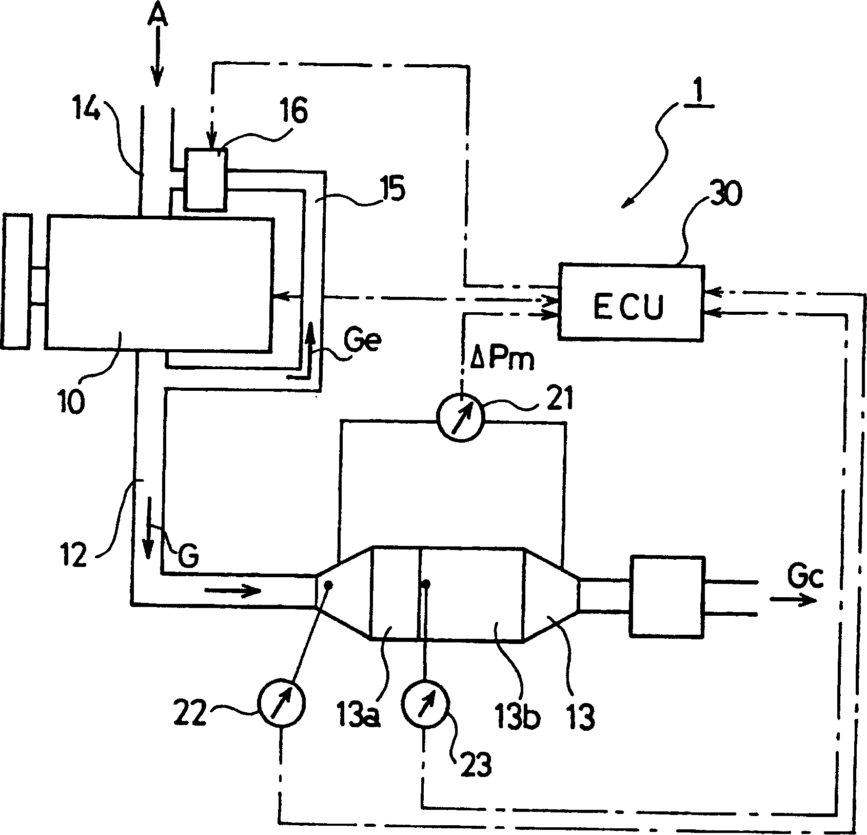
[0026] figure 1 The structure of the exhaust gas purification system 1 for an internal combustion engine of this embodiment is shown. In the diesel engine 10 provided with this exhaust gas purification system 1 , an EGR passage 15 of an EGR valve 16 is provided from the exhaust passage 12 toward the intake passage (intake pipe) 14 side. Further, a continuous regeneration type DPF 13 is provided in the exhaust passage 12 of the diesel engine 10 . The continuous regenerative DPF 13 has an oxidation catalyst (DOC) 13 a on the upstream side and a catalyst-carrying filter (CSF) 13 b on the downstream side.

[0027]...


PUM


Abstract

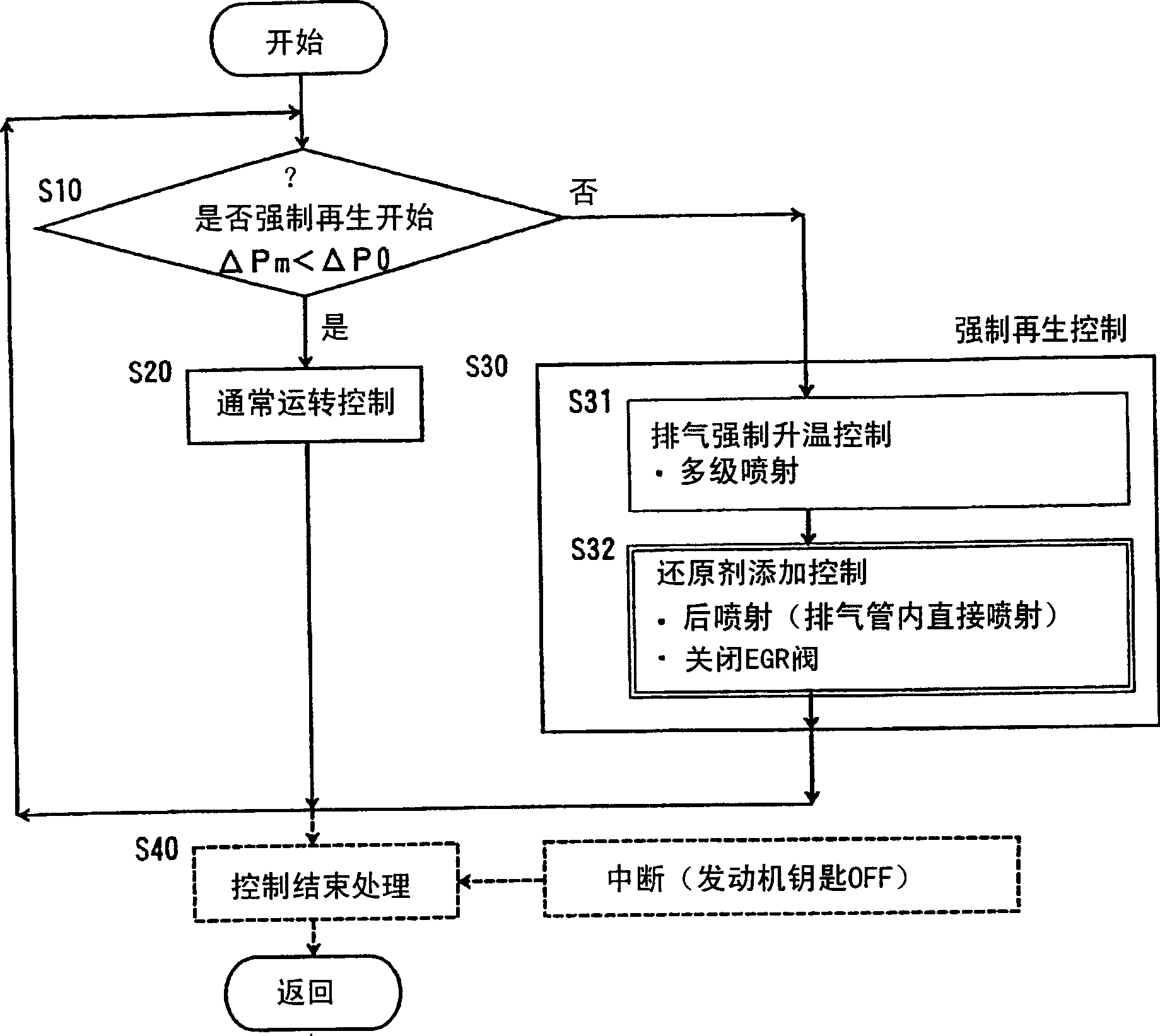
This invention provides a method for controlling an exhaust emission control system and the exhaust emission control system capable of preventing damage of an engine caused by blockage of an EGR passage and adhesion of an intake valve or the like which occur due to imperfect combustion of unburned fuel or the like supplied to exhaust gas by preventing the blockage of the EGR passage, adhesion of the intake valve or the like in forced regeneration control of a continuous regeneration type DPF device. In the exhaust emission control system 1 having the continuous regeneration type DPF device 13 including a filter 13b collecting PM in exhaust gas G provided in an exhaust gas passage 12 of an internal combustion engine 10 equipped with an EGR system and supplying unburned fuel to the exhaust gas G flowing in the continuous regeneration type DPF device 13 at a time of forced regeneration for regenerating the filter 13b by forcedly burning PM collected by the filter 13b, circulation of EGR gas Ge to an intake air passage 14 side by the EGR system is stopped at a time of unburned fuel supply to the exhaust gas G in forced regeneration control.

Description

technical field [0001] The present invention relates to a control method and an exhaust gas purification system for purifying particulate matter (PM) by a continuously regenerative diesel particulate filter (DPF) on exhaust gas from an internal combustion engine such as a diesel engine. Background technique [0002] The amount of particulate matter (PM: particulate matter: hereinafter referred to as PM) emitted from diesel internal combustion engines and NO x , CO and HC, etc., the restrictions are being strengthened year by year, and a filter called Diesel Particulate Filter (DPF: Diesel Particulate Filter: hereinafter referred to as DPF) has been developed to trap this PM to reduce A technique to measure the amount of PM discharged to the outside. [0003] The DPF that captures this PM has a ceramic monolithic honeycomb-type wall-flow filter, or a fiber-type filter made of ceramic or metal fibers, and the exhaust gas purification system using these DPFs is the same as oth...

Claims


Application Information

Patent Timeline
Patent Type & Authority Applications(China)
IPC IPC(8): F02M25/07F01N3/02F01N3/023F01N3/025F02D21/08F02D41/00F02D41/02F02D41/40
CPCF02D41/029F02D41/405F01N3/0231Y02T10/47F02D41/0055F01N3/0253Y02T10/40
Inventor 长谷山尊史松沼厚伍维岩下拓朗小野寺贵夫池田秀
Owner ISUZU MOTORS LTD
Learn More