
Mechanical automatic vertical drilling tool

A vertical drilling and mechanical technology, applied in directional drilling and other directions, can solve the problems that vertical well drilling has not been well solved, cannot meet the needs of vertical well drilling, and is difficult to popularize and use.

Inactive Publication Date: 2005-10-05
SHENGLI PETROLEUM ADMINISTRATION BUREAU DRILLING TECH ACAD SINOPEC
View PDF0 Cites 39 Cited by
  • Summary
  • Abstract
  • Description
  • Claims
  • Application Information

AI Technical Summary

Problems solved by technology

However, after years of development in modern drilling, the problem of vertical well drilling has not been well resolved. Vertical well deflection prevention is a ubiquitous and very prominent problem.
[0003] At present, the deflection control of conventional vertical wells is mainly to use the full hole combination "heavy pressure and fast drilling" to maintain the straightness at full capacity, and the pendulum combination "light pressure lifting" is used to correct the deflection slowly. The disadvantage is that it sacrifices the drilling pressure and high cost. In exchange for small well deviation, in exchange for well quality at the expense of ROP, well quality and economic benefits are opposite
Although there have also appeared tower drilling tools, square drill collars, eccentric drill collars, HCY anti-deviation devices, off-axis anti-deviation fast drilling technology, flexible combination anti-deviation fast drilling technology, directional drilling tool anti-deflection fast drilling technology and anti-clockwise pendulum anti-drilling technology. Oblique hitting fast technology and other technologies, but due to certain limitations, it is difficult to popularize and use
[0004] Due to the limited scope of application of conventional vertical well deviation prevention and correction technology, it can no longer meet the needs of drilling vertical wells in complex situations such as high and steep structures and deep wells

Method used


Image

  • Mechanical automatic vertical drilling tool

Examples


Embodiment Construction

[0010] The present invention will be further described now in conjunction with the accompanying drawings of the description.

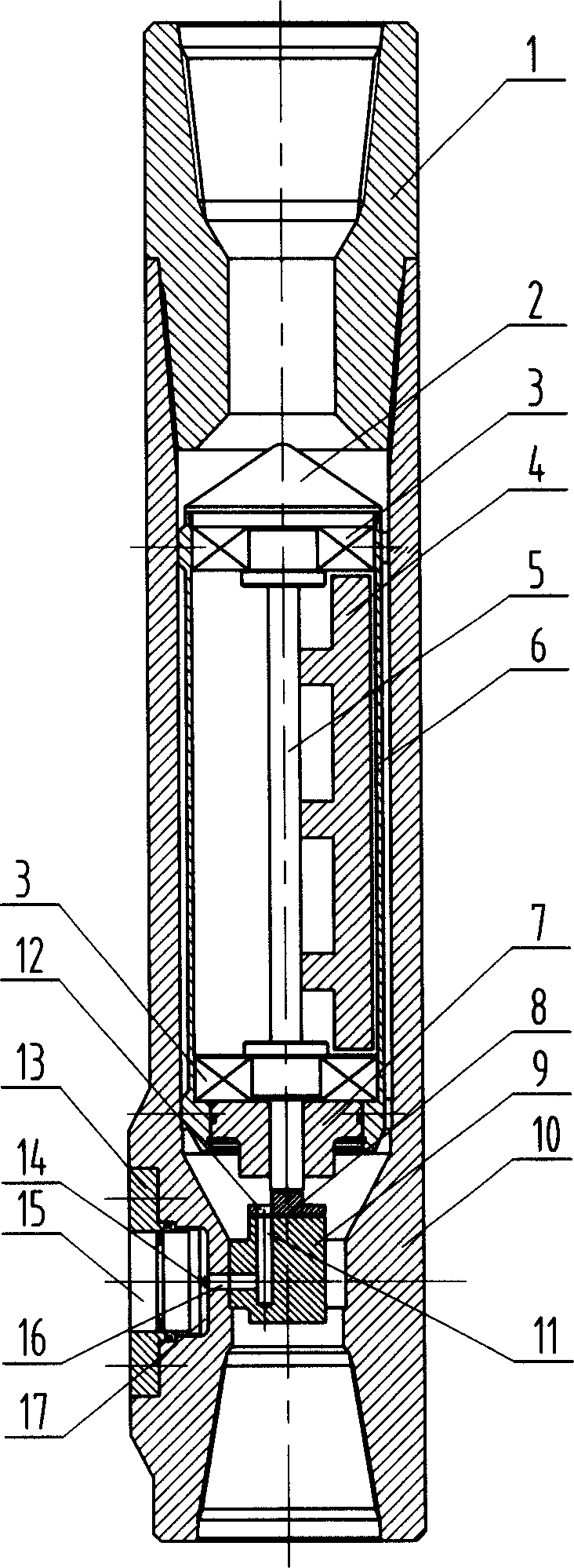
[0011] When using the present invention to carry out vertical well drilling construction, the bearings [3] are mounted on both ends of the mandrel [5], the counterweight [4] is fixed on one side of the mandrel [5] and between the bearings [3], and then the mandrel [5], the bearing [3] and the counterweight [4] are put into the inner cylinder [6] together, the guide head [2] is fixed on the upper end of the inner cylinder [6], and the inner cylinder baffle [7] is set on the mandrel [5] ], and fixed with the inner cylinder [6], the upper disc valve [8] is connected with the lower end surface of the mandrel [5], the fan-shaped eccentric flow channel [12] and the counterweight [4] of the upper disc valve [8] Located on both sides of the mandrel [5] respectively, a piston cylinder [17] is processed on the outer wall of the lower end of the housing [10], the...


PUM


Abstract

One kind of mechanical type automatic vertically well-drilling tool, including turner, the conduction current head, the bearing, the counterweight, the spindle, in-tube, the back plate, above plate-valve, gets down plate-value, the shell, the piston cylinder back plate and the piston, its principle is at the right moment induces the well slanting gravity signal, by the gravity-actuates in the organization, the establishment drills inside and out the column high-low pressure channel between the fluid, uses two between the differential pressure, actuates the piston at the right moment to push depends on the wall of a well is high side, the wall of a well reacting force then pushes the drill bit to is low side, but in well-eye other positions, the piston does not push depends on the wall of a well, drills the column revolves, this process circulation reciprocation, the well is slanting namely is unceasingly induced and the revision, this invention realization is initiative, At the right moment guards against slanting at the same time, but also can effectively liberate distilling, largely enhances drills fast and well-eye the quality, reduces the construction risk, this invention has the structure is simple, reliable, is suitable to the many kinds of well drilling platform, the processing makes the maintenance cost is low and so on the characteristic.

Description

technical field [0001] The invention belongs to a supporting device for oil and natural gas drilling. technical background [0002] Vertical wells are the first type of oil and gas wells with the largest number at present. According to statistics, vertical wells account for at least 55% of the world's drilling wells. In 2004 alone, there were more than 50,000 vertical wells in the world (excluding China). However, after many years of development in modern drilling, the problem of vertical well drilling has not been well resolved, and vertical well deflection prevention is a ubiquitous and very prominent problem. [0003] At present, the deflection control of conventional vertical wells is mainly to use the full hole combination "heavy pressure and fast drilling" to maintain the straightness at full capacity, and the pendulum combination "light pressure lifting" is used to correct the deflection slowly. The disadvantage is that it sacrifices the drilling...

Claims


Application Information

Patent Timeline
IPC IPC(8): E21B7/10
Inventor 倪红堅韩来聚马清明
Owner SHENGLI PETROLEUM ADMINISTRATION BUREAU DRILLING TECH ACAD SINOPEC
Learn More