Equipment for reacting sputtering

A kind of equipment and reaction technology, applied in the field of reactive sputtering equipment, can solve the problem of low sputtering rate

Inactive Publication Date: 2005-09-28
APPLIED MATERIALS INC
View PDF4 Cites 5 Cited by
  • Summary
  • Abstract
  • Description
  • Claims
  • Application Information

AI Technical Summary

Problems solved by technology

On the contrary, in most cases, the sputtering rate of the reaction product is generally lower than that of the pure metal

Method used


Image

  • Equipment for reacting sputtering
  • Equipment for reacting sputtering
  • Equipment for reacting sputtering

Examples


Embodiment Construction

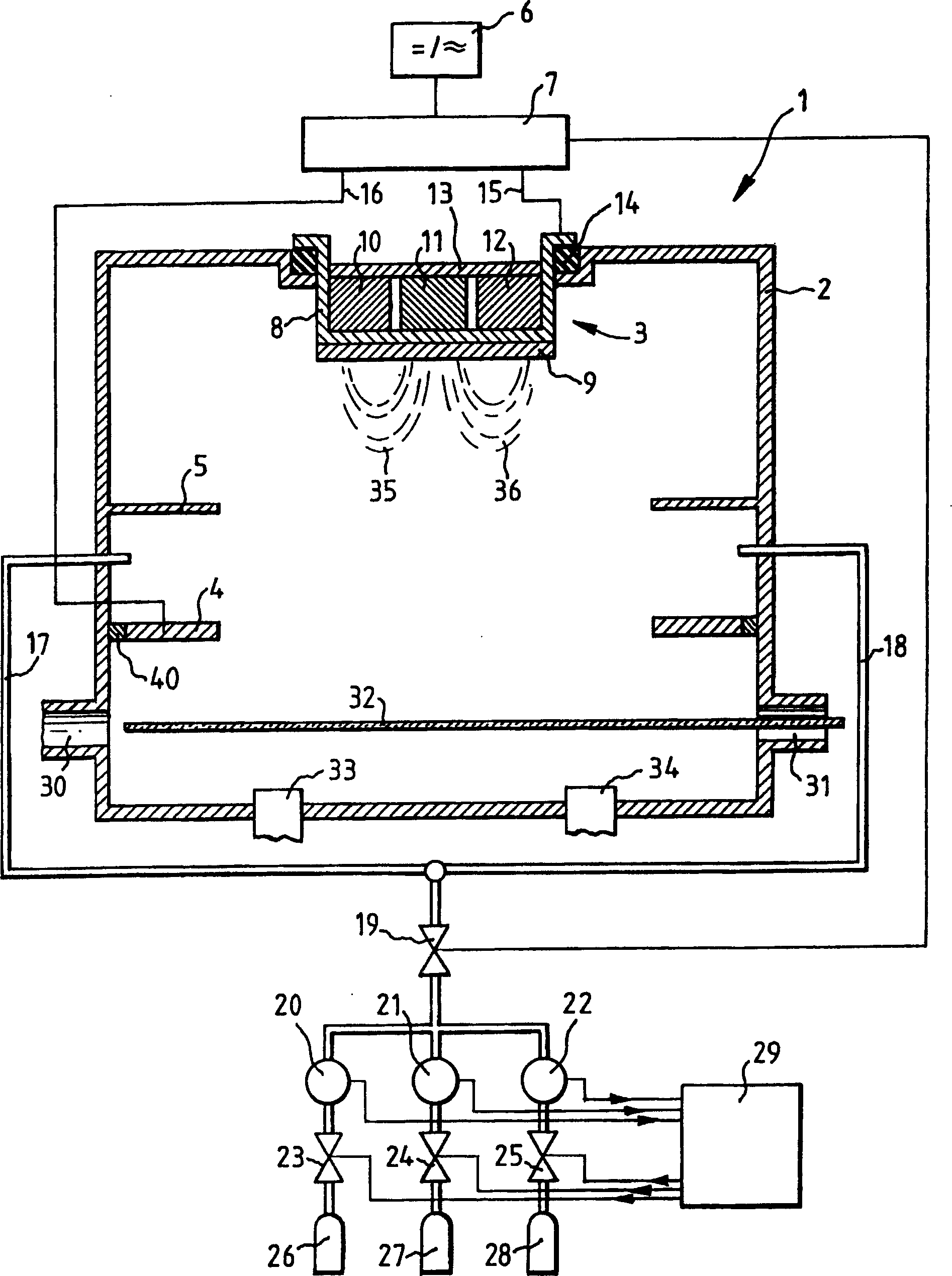
[0022] figure 1 The principle of the sputtering device 1 is shown, and the sputtering device 1 includes: a sputtering chamber 2 , a cathode 3 , an anode 4 , a protective plate 5 , a voltage source 6 and a regulating circuit 7 . The cathode 3 comprises a tubular cathode part 8 to which a target 9 to be sputtered is mounted by means of a flange. Three permanent magnets 10 , 11 , 12 are arranged on the tubular cathode part 8 , and the three permanent magnets 10 , 11 , 12 are connected to each other via a yoke 13 . The cathode part 8 bears on a seal 14 on the edge of the opening in the sputtering chamber 2 . The voltage of the voltage source 6 is conducted via one electrode 15 of the regulating circuit 7 to the cathode part 8 and via its other electrode 16 to the anode 4 . Even if the voltage of the voltage source 6 fluctuates, the regulation circuit 7 keeps the voltage output to the anode-cathode path constant. The fluctuation of the discharge voltage is mainly affected by the...


PUM


Abstract

A device for reactive sputtering, wherein a cathode is applied a discharge voltage for a plasma, and a working gas and a reactive gas are introduced into a sputter chamber. The total gas flow in the sputter chamber is controlled with the aid of a valve, while the ratio of the partial pressures of both gases is kept constant.

Description

technical field [0001] The invention relates to a device for reactive sputtering according to the preamble of patent claim 1 . Background technique [0002] Usually, in reactive sputtering, at least two gases are used: a gas, which in most cases is usually an inert gas, and which excites particles outside the target in ionized form; Compounds are formed. The compound is then deposited as a thin film layer on a substrate, such as a glass plate. [0003] In order to accelerate ions of a noble gas to a target, a voltage must be applied to the target. The voltage between the target and the counter depends inter alia on the gas pressure obtained within the sputtering chamber. If the non-conductive substrate to be coated is moving within the sputtering chamber, this voltage also depends on the specific position of the substrate. [0004] Therefore, the dependence of voltage on pressure can be interpreted as, at high pressure, atoms are still present in the gas volume, so that ...

Claims


Application Information

Patent Timeline
Patent Type & Authority Applications(China)
IPC IPC(8): C23C14/34C23C14/00C23C14/54C23C14/56
CPCC23C14/0042
Inventor 托马斯·弗里茨冈特·克梅雷尔
Owner APPLIED MATERIALS INC
Why Eureka
Try Eureka