Charging line structure of new energy automobile

A technology of new energy vehicles and charging lines, applied in the direction of electric vehicle charging technology, electric vehicles, circuits, etc., can solve the problems of crushing, troublesome charging line structure, small charging range, etc., and achieve the effect of convenient use and simple structure

Inactive Publication Date: 2018-01-09
SHENZHEN CITY HAIDUN HARDWARE TOOLS CO LTD
View PDF5 Cites 0 Cited by
  • Summary
  • Abstract
  • Description
  • Claims
  • Application Information

AI Technical Summary

Problems solved by technology

[0002] Cars generally use gasoline and diesel, but gasoline and diesel are non-renewable resources, and the exhaust gas after burning gasoline and diesel is likely to cause air pollution. Therefore, people pay more and more attention to new energy vehicles, and pure electric vehicles have become new energy sources. The main force of automobiles, pure electric vehicles use a single battery as an energy storage power source without using gasoline or diesel, so they will not emit pollutants and cause air pollution. Therefore, strongly supported by national policies, pure electric vehicles need To charge the storage battery, the existing pure electric vehicles generally use charging piles for charging. The charging lines on the existing charging piles are generally of fixed length. Therefore, the charging range is fixed. If the charging line is too long When the charging line is too short, the charging range is small. In many cases, when the car is parked far away, it is necessary to restart the car and move it closer before charging. Therefore, the traditional The structure of the charging line is troublesome to use, and there are major disadvantages

Method used


Image

  • Charging line structure of new energy automobile
  • Charging line structure of new energy automobile
  • Charging line structure of new energy automobile

Examples


Embodiment Construction

[0022] All features disclosed in this specification, or steps in all methods or processes disclosed, may be combined in any manner, except for mutually exclusive features and / or steps.

[0023] Any feature disclosed in this specification (including any appended claims, abstract and drawings), unless expressly stated otherwise, may be replaced by alternative features which are equivalent or serve a similar purpose. That is, unless expressly stated otherwise, each feature is one example only of a series of equivalent or similar features.

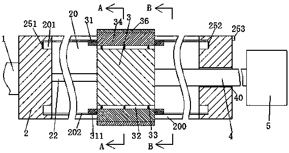
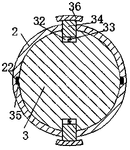
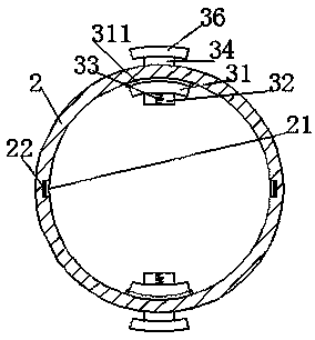
[0024] Such as Figure 1-4 As shown, a new energy vehicle charging line structure of the present invention includes a fixed cable 1 fixedly connected to the charging pile, a charging plug 5 connected to the new energy vehicle, and an adjustment cylinder 2, and the adjustment cylinder 2 is provided with The adjustment sliding chamber 20 extending left and right, the adjustment sliding chamber 20 is symmetrically provided with the adjustment gr...


PUM


Abstract

The invention provides a charging line structure of a new energy automobile. The structure comprises a fixed cable fixedly connected with a charging pile, a charging plug connected with the new energyautomobile and an adjusting cylinder. A left-right extending adjusting sliding cavity is arranged in the adjusting cylinder. Adjusting grooves which communicate with the adjusting sliding cavity andextends leftwards and rightwards are up-down symmetrically arranged in the adjusting sliding cavity. An adjusting sliding block is installed in the adjusting sliding cavity in a left-right slidable manner. A movable cable is fixedly installed on the right end of the adjusting sliding block, rightwards passes a through hole arranged in the right end of the adjusting cylinder and then is fixedly connected with the charging plug. A left-right extending strip-shaped groove is arranged in the inner wall of the adjusting sliding cavity. Strip-shaped conductive sheets are fixedly installed in the strip-shaped grooves. A left-right extending conductive contact sheet is arranged on the periphery of the adjusting sliding block, can be installed in the strip-shaped grooves in a left-right slidable manner and is abutted against the strip-shaped conductive sheets. According to the invention, the extending length of the movable cable can be freely adjusted.

Description

technical field [0001] The invention relates to the field of new energy vehicle charging equipment, in particular to a new energy vehicle charging line structure. Background technique [0002] Cars generally use gasoline and diesel, but gasoline and diesel are non-renewable resources, and the exhaust gas after burning gasoline and diesel is likely to cause air pollution. Therefore, people pay more and more attention to new energy vehicles, and pure electric vehicles have become new energy sources. The main force of automobiles, pure electric vehicles use a single battery as an energy storage power source without using gasoline or diesel, so they will not emit pollutants and cause air pollution. Therefore, strongly supported by national policies, pure electric vehicles need To charge the storage battery, the existing pure electric vehicles generally use charging piles for charging. The charging lines on the existing charging piles are generally of fixed length. Therefore, the...

Claims


Application Information

Patent Timeline
Patent Type & Authority Applications(China)
IPC IPC(8): H01R13/72H01R25/14H01R13/717B60L11/18
CPCY02T90/12
Inventor 戚祖盛
Owner SHENZHEN CITY HAIDUN HARDWARE TOOLS CO LTD
Why Eureka
Try Eureka